Membrane Switch Defined

Membrane Switch Defined

What is a Membrane Switch?

membrane switch is an interface between man and machine, enabling an operator to communicate with equipment, instrumentation, or machinery. A membrane switch is a printed or etched electronic circuit that uses pressure to open and close a circuit. The membrane switch circuitry can be: screen printed using conductive inks which are typically made of silver or carbon, etched copper on Kapton, or can be printed circuit board based. The membrane switch overlay is typically made of polyester, polycarbonate, or molded silicone rubber. Membrane switches are part of a range of devices considered to be user interfaces or human machine interfaces (HMIs) along with touch screens and mechanical switches.

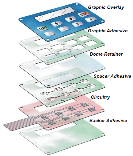
Membrane Switch Construction

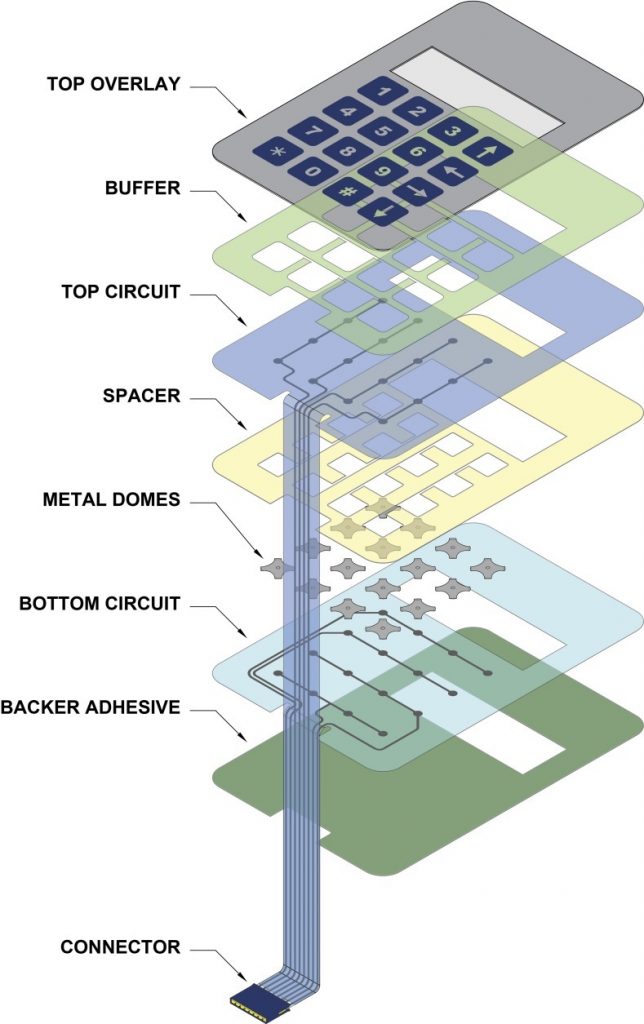
A typical membrane switch assembly typically consists of six to seven main layers:

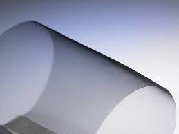
  • Graphic Overlay – Graphic overlays are typically constructed of polyester, the material of choice due to its superior chemical resistance and flex life compared to polycarbonate. CSI can either digitally print, screen-print, or employ a combination of both methods to insure you get the right colors, textures, and finishes your Silver Flex membrane switch design requires.
  • Overlay Adhesive – The overlay adhesive layer bonds the graphic overlay to the top circuit layer. This overlay adhesive is typically an acrylic adhesive, selected for its durability and ability to maintain adherence in atypical environments, such as moist environments.
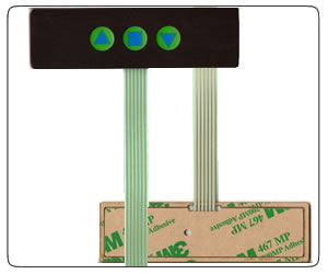
  • Top Circuit Layer – Typically a .005″ – .007″ heat-stabilized, polyester printed layer with silver-filled, electrically conductive inks and dielectric inks. This layer can also encapsulate metal domes or incorporate polydomes, which are used to achieve tactile feedback, an important design consideration impacting usability.
  • Circuit Spacer – This layer separates the top circuit from the bottom circuit, so the switch remains normally open until the keypad is pressed. The circuit spacer is a polyester spacer with adhesive on both sides.
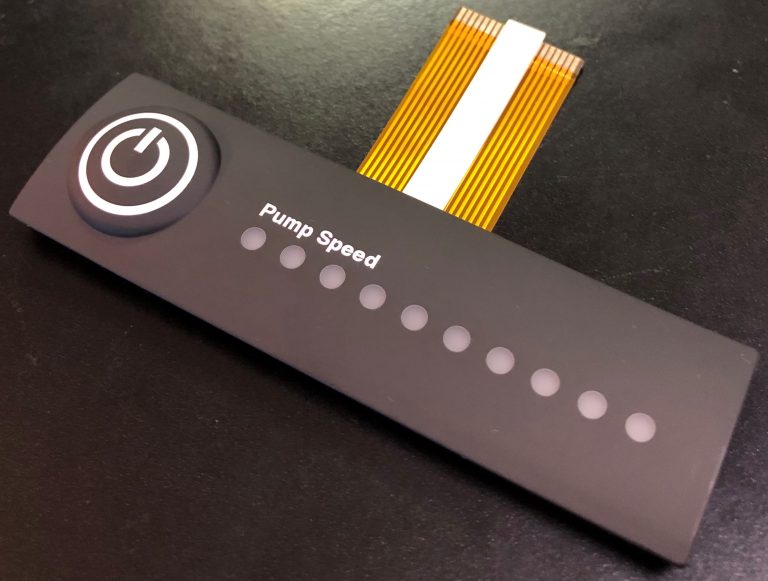
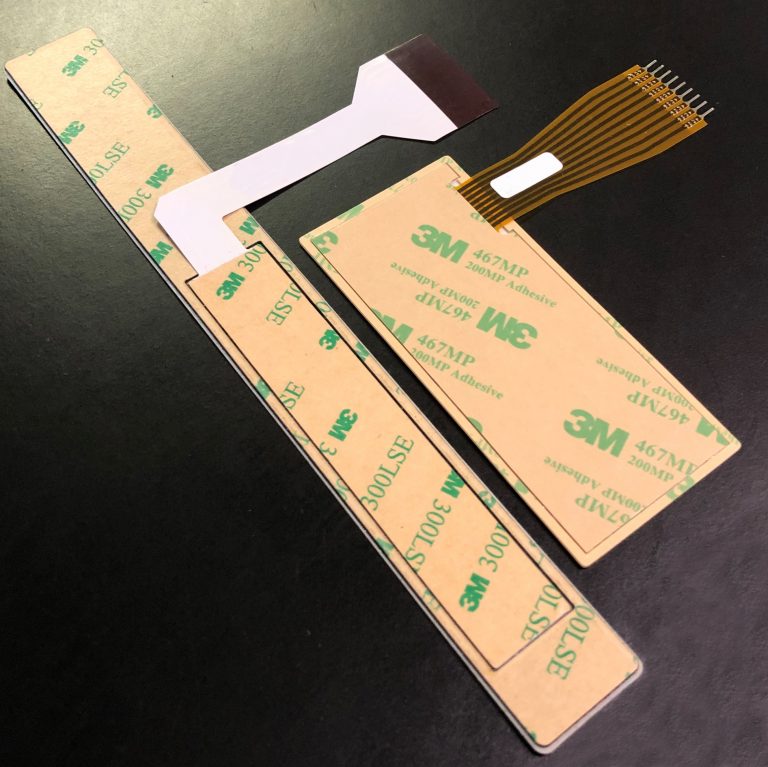
  • Lower Circuit Layer – The lower circuit layer is typically a .005″ – .007″ heat-stabilized, polyester-printed layer with silver-filled electrically conductive inks and dielectric inks. This layer terminates as a flexible tail that serves as the interconnect to controller PCB’s or other electronics.
  • Rear Adhesive Layer – This adhesive layer bonds the entire membrane switch package to the product enclosure, housing, or to a rigid support panel. CSI can specify the appropriate adhesive type and thickness to bond your membrane keypad to your equipment.
  • Rigid Support Layer – This optional layer can add structural integrity to the membrane switch assembly. Materials can be aluminum, FR-4, steel, etc. Mounting hardware such as studs and standoffs can also be utilized in this layer.
Membrane Switch Guide

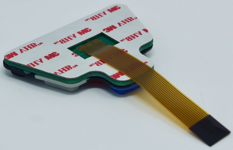
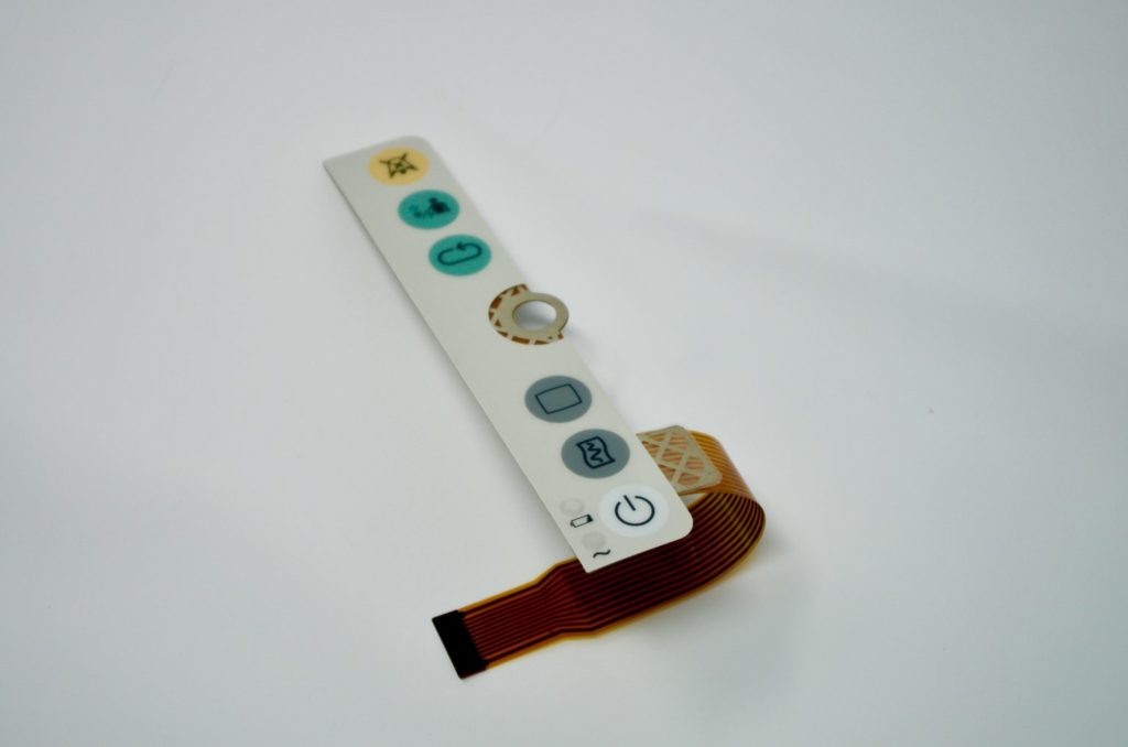
Copper Flex Membrane Switches

The Copper Flex Membrane Switch constructions are ideal for smaller designs, where space is at a premium, or where dense circuit patterns or trace routing limitations exist. Copper Flex membrane keypads utilize silver or copper layers which are laminated to a dielectric layer and etched away.

This switching technology combines the ability to accommodate the complex circuit patterns of a FR4 rigid printed circuit board with the flexibility of a membrane switch. Copper Flex keypads also have the advantage of being able to “hard” solder both active and passive components into the assembly, making it a good choice in high-vibration environments.

Copper Flex membrane switch panels can be produced using polyester or polyimide (Kapton) as the base material depending on your interface requirements. A very thin sheet of copper is laminated to the flexible film substrate then chemically etched away, leaving copper traces. 

Copper Flex membrane switches offer you a variety of design options:

  • Single and double sided designs
  • Lower electrical resistance and higher conductivity vs. traditional Silver Flex membrane switches
  • Tight trace routing capabilities
  • Thin profile and flexibility of Silver Flex membrane switch
  • Plating options can be tin-lead, nickel, or gold
  • Tactile and non-tactile with either metal or polyester tactile domes
  • LED’s and other components can be soldered
CSI Keyboards Medical Membrane Switch

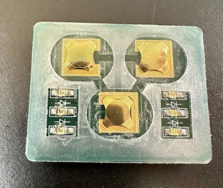
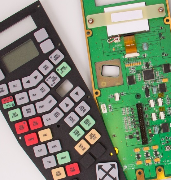
PCB Based Membrane Switches

The PCB Membrane Switch construction utilizes a printed circuit board (PCB) which can serve a dual purpose in your membrane switch design. PCB Switches are typically more costly than Silver Flex membrane keypads, but can accommodate dense circuit patterns and more complex circuit patterns compared to Silver Flex membrane keypads.

A PCB membrane switch also allows the electronic components to be “hard-soldered” into the PCB, whereas membrane switch components are placed using a polymer thick film conductive paste. With a PCB membrane switch, the PCB can serve as a rigid backer, and is also a very durable and reliable method to incorporate LED’s, resistors, LCD’s and other components.

CSI Keyboards PCBA Rubber Keypad

PCB membrane keyboards offer you a variety of design options:

  • Tactile and non-tactile with either metal or polyester tactile domes
  • Pillow or rim-embossed graphic overlays
  • Embedded LED’s that are soldered directly into the PCB
  • Fiber Optic backlighting
  • EL – (Electroluminescent backlighting)
  • Rigid backers such as aluminum and FR4
  • EMI/RFI shielding
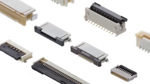
  • Unlimited choice of connectors, which can be soldered directly into the PCB

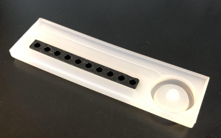
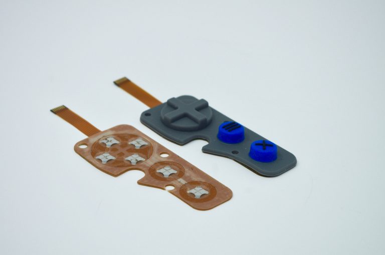
Silicone Elastomer Rubber Keypads

Silicone rubber keypads use compression-molded silicone rubber with conductive carbon pills or with non-conductive rubber actuators.  They have exceptional resistance to extreme temperatures and aging, making them an ideal choice if reliability is a prominent concern due to likely environmental influences.

A rubber membrane switch uses compression-molded silicone rubber with conductive carbon pills or with non-conductive rubber actuators. Rubber keypads are relatively inexpensive on a per-piece basis, but require fairly expensive tooling, usually making them a design choice for higher-volume projects.

Silicone rubber keypad switches have numerous features that set this type apart from other traditional membrane switch designs. Some of the main differentiating features of this type make the silicone rubber keypad switch an ideal choice for applications requiring more durability or better resistance to exposure to moisture, chemicals, or other compounds.

Molded rubber keypad: copper flex circuit based with domes and backlit keys

Some of the primary distinctive features of silicone rubber keypad switches include:

  • Work as a conductive shorting device for Silver Flex membrane switchesPCB membrane switches, and Copper Flex membrane switches
  • Can utilize carbon pills, non-conductive rubber actuators, or stainless steel tactile domes
  • Actuation forces and switch travel can be customized
  • Any shape or size can be designed
  • Multiple colors can be achieved by flow molding the color during the compression-molding process
  • Rubber keypad top graphics can be customized by screen-printing
  • Rubber keypad switches can be PU spray-coated for enhanced durability
  • Rubber membrane switches have excellent weatherability for outdoor use
  • Can be designed to seal the keypad assembly from moisture and contaminants
  • Silicone rubber is resistant to chemicals and moisture
  • Laser etching the rubber keypads can allow for backlighting individual keypads
  • Backlighting options

Utilizing Mesh for Keypad EMI Shielding

Utilizing Mesh for Keypad EMI Shielding ​

Do you have a product that has stringent EMI shielding requirements? CSI can integrate EMI mesh into your keypad assembly using the finest woven blackened wire mesh. The mesh is blackened to make it suitable for optical applications such as applying over displays or under windows. 

EMI protection will be provided by covering the entire keypad, display and LED conductors, etc. with wire mesh. The mesh is typically 80 x 80 density, of .0011 inch diameter stainless steel wire strands.  It is an interwoven fabric, silver coated, and then blackened. The mesh shall be in direct electrical contact when attached to the enclosure. The woven mesh is highly conductive for the best EMI shielding effectiveness and is even and very black avoiding highly reflective un-blackened wires and discolorations.

Integrating the Mesh into the Design:

  1. The mesh is die-cut to the shape of the keypad and then assembled into the internal layers of the keypad assembly.
  2. CSI will work closely with you in determining the best method to make direct electrical contact between the EMI mesh and your product when the keypad is assembled to your enclosure.
Membrane Switch with EMI Mesh

Redesigning your Existing Membrane Switch

Redesigning your Existing Membrane Switch​

Every week, we are approached by a customer that is having issues with a membrane switch or keypad designed by another manufacturer. More often than not, the membrane switch was not engineered properly when it was originally developed. Typically, the membrane switch is failing out in the field due moisture ingress and lack of sealing characteristics.

Because this is such a common occurrence, CSI has a seamless process in place for redesigning your current membrane switch without having to completely reinvent the wheel. We can work closely with your company in designing a drop-in replacement that will not require any product redesign or any changes for that matter on your end. CSI will update and upgrade all of the critical internal layers giving you the environmental sealing required while leaving the external layers untouched – leaving you with a completely sealed product upgrade that can be smoothly incorporated into your existing production line.

So what you waiting for?! If you are unhappy with your current membrane switch, now is the time to make the change. Reach out to CSI today to get the ball rolling and eliminate these headaches once and for all!

What are the Internal Layers of Membrane Switches?

What are the Internal Layers of a Membrane Switch?​

We all know about the graphic overlay layer which is the top surface of the keypad that always gets the most attention (and rightfully so).  But what’s going on behind the scenes in the sub-assembly of the membrane switch?  Let’s find out.

Dome Retainer Layer

The dome retainer layer is somewhat self explanatory. The primary function of this layer is hold the metal domes in place and position. It is typically manufactured from polyester film material.

Spacer Layer

The spacer layer is used to created a break in contact between the two conductors of the switch. This allows the switch to have its open position. The spacer design typically includes vents or channels to prevent air entrapment in the layers when the keys are pressed or actuated.

Circuit Layer

The circuit layer is the electrical aspect of a membrane switch where the conductive traces are applied using one of the two main methods of application: screen printing and photochemical etching.

  • Screen Printing or Printed Silver Circuitry: Silver conductive ink is flooded on the stencil placed above a substrate (typically polyester film).
  • Photochemical Etching or Copper Flex Circuitry: Copper laminated substrate is selectively created through photolithography and a chemical etching process.

Designing a Sealed & Backlit Rubber Keypad​

Designing a Sealed & Backlit Rubber Keypad​

Designing a rubber keypad that is both backlit and completely sealed may seem like a daunting task, but that’s what the experts at CSI are here for!  There are essentially two main components of the keypad assembly that must be properly designed: the rubber and the circuit. To better speak to the process, we will use the sample keypad on the right side of this post.


Rubber Decorating Process:

  1. The rubber starts off as a clear/milky translucent color (the color of the base material). The black portions of the keypad are rubber light blocks that are molded into the rubber to prevent light from bleeding into other portions of the keypad.
  2. The rubber is then sprayed translucent white.
  3. The rubber is then sprayed opaque black and then laser etched down to the translucent white material (for the power button) and hte clear base material (for the LED indicators) in the areas that are backlit.
  4. The rubber is carefully designed so that the actuators on the back of the keys press into the metal dome switches efficiently. 
  5. The rubber is also designed so that it provides a seal. Silicone is typically used for gasketing in many products, so why not utilize it’s properties for the same reasons in your keypad?!
  6. The rubber is then sprayed with a UV resistant coating that protects the keypad from ultraviolet exposure, while also providing chemical resistance. 


Additional Sealing Features:

Copper Flex Circuitry, also known as polyimide Kapton circuitry, are used in the majority of CSI Keyboards’ keypad designs due to its excellent dielectric strength, thermal stability, chemical resistance and flexibility. Copper Flex membrane switch panels are produced using polyimide (Kapton) as the base material. Copper flex switches are manufactured by laminating a thin sheet of copper to a flexible film substrate. The copper is then chemically etched away, leaving the copper traces. An additional layer of polyimide is laminated to the circuit leaving the gold contacts exposed. Copper flex has become the superior choice over printed silver especially for outdoor applications. Copper flex circuitry construction designs offer a significant advantage over printed silver and a printed silver circuit can be replaced with a copper and polyimide construction with minimal additional cost.

Seal Frame is a perimeter frame of adhesive that protects your circuitry from any moisture ingress. It have proven to be as robust as other sealing methods such as perimeter temperature sealing and can be included in your design at minimal additional cost.

PU (polyurethane) Coating was applied, which protects the printed and molded colors on the rubber keypad, and also increases the longevity of the printing and graphics. This coating ensures a longer keypad life regardless of the environment. We also utilize a proprietary coating specially formulated for marine and outdoor applications which provides added protection against UV exposure.

Rear 3M 300LSE Adhesive was utilized, which is the top of the line adhesive specially formulated to provide high bond strength to surfaces. Our adhesives are resistant to humidity, UV, water, temperature, and chemicals.

EMI/RFI and ESD Protection is obtained using a metalized Mylar shield layer. A separate tail for the shielding layer was designed to connect to the housing or another mechanical piece already grounded. Another option could have been grounding to a trace on the interface panel and then routed to a grounded plane on the motherboard to carry the static charge away from any nearby conductive components.

Silver Migration in Membrane Switches​

Silver Migration in Membrane Switches​

Silver Migration Explained:

Printed silver is a metal that has been used in the flexible circuit aspect of membrane switches for over 35 years. The conductive silver is screen printed on flexible substrates (typically polyester or polycarbonate) to form the conductive traces that are the electrical backbone of a membrane switch. Silver is still widely prevalent in membrane switch designs to this day due to its conductivity, usability and cost-effectiveness.

There are some disadvantages to using printed silver, however. Silver is a very active metal and is thus highly susceptible to silver migration or dendritic growth. Silver migration is the ionic movement of silver between two adjacent traces on the circuit. Silver migration will occur if there is moisture present between the two traces which results in a temporary electrical short. The rate of migration depends on the amount of moisture, the temperature and the voltage.

Preventing Silver Migration:

While silver migration can be a major headache for membrane switch users around the world, conductive silver certainly would not have been used in keypads for over three decades if there wasn’t a solution:

  • Prevention is the ultimately the best solution. Preventing moisture ingress into the circuit will prevent silver migration from ever occurring. Properly designing the membrane switch using a frame seal is one of many methods CSI utilizes to prevent your keypad from silver migration.
  • Utilizing copper flex circuitry instead of printed silver circuity.
  • Covering the silver traces with a protective carbon layer and/or an overcoat dielectric.
  • Increasing the conductor spacing between traces on the circuit.
  • Reducing the voltage.

Hot Bar Solder Lamination: What is It and Why Utilize It?

Hot Bar Solder Lamination: What is It and Why Utilize It?

Our customers sometimes require a membrane keypad with a connection that calls for flex circuits directly connected to rigid boards versus using connectors. Connecting a flexible circuit directly to a printed circuit board requires a manufacturing procedure called hot bar solder or heat seal lamination. There are many benefits for using a direct flex-to-board connection. 

The Main Benefits of Hot Bar Solder Lamination:

1. Saves vertical height in the design

2. Fast temperature ramp-up and cool-down 

3. Closed loop temperature control

4. Can be more reliable than fine pitch connectors

5. Accurate positioning of the parts

6. Multiple connections can be made simultaneously

7. Cost effective due to elimination of third component such as connector

ZIF Connectors on Membrane Switches: What Are They, What Do They Do?

ZIF Connectors on Membrane Switches: What are They & What do They do?

ZIF connectors have no physical connector on your membrane switch and rely on a receptacle connector that is available from numerous manufacturers. It is important to choose a ZIF connector that is suggested for membrane switches and to keep in mind that smaller pitches are available in polyimide flexible printed circuits only.

ZIF connectors are increasingly common in several applications, especially when connecting to a small display or keyboard. ZIF connectors meet a range of requirements including low profile, lightweight, secure, and removable connections. ZIF connectors are appropriate for more complex applications and allow for higher levels of integration. For ZIF connections, the connector system is not on the membrane tail, but on the PCB. The tail of the circuit is inserted into the ZIF connector to create the contact, and a stiffener is laminated under the tail to ensure stability and maintenance of the electrical contact. ZIF connectors may have anywhere from 2 to 30 positions on a single row, and distances of between 1mm and 2.54 mm are available.

Keep in mind that ZIF connections degrade with insertions, so the maximum number of insertions should not exceed 10 cycles. It’s also important to remember to take care when placing the tail die but in relation to the printed traces, since resistance in the circuit may increase in spacing of less than 1mm where the circuit traces are thinner.

Key Flex Circuit Terms That You Should Know

Key Flex Circuit Terms That You Should Know

CSI Keyboards uses copper flex circuitry in the majority of our custom keypad designs due to its excellent dielectric strength, thermal stability, chemical resistance and flexibility. Copper flex, also known as Kapton circuits, have become the superior choice over printed silver especially for outdoor applications. A printed silver circuit can be replaced with a copper and polyimide construction with minimal additional cost. Copper flex circuitry construction designs offer a significant advantage over printed silver. 

Below are some key flex circuit terms that you should know:

Access Hole – A series of holes in successive layers of a multilayer board, each set having their centers on the same axis. These holes provide access to the surface of the land on one of the layers of the board.

Additive Process – A process for obtaining conductive patterns by the selective deposition of conductive material on clad or unclad base material.

Annular Ring – The ring of exposed solder or copper around a through hole.

Buried Via – A plated through hole buried within internal layers of a circuit. There is no direct access to the via.

Blind Via – A plated interconnection from one layer to an adjacent layer through a fixed depth LASER drilled opening.

Cantilevered Leads – Unsupported conductors extending from an edge of a flex circuit.

Circuit – A number of electrical elements and devices that have been interconnected to perform a desired electrical function.

Coverlayer – Insulating layer usually bonded with adhesive.

Dielectric – A material with a high resistance to the flow of direct current, and which is capable of being polarized by an electrical field.

Flexible Printed Circuit – A patterned arrangement of printed circuitry and components that utilizes flexible base material with or without flexible coverlay.

Land – A portion of a conductive pattern usually used for the connection and/or attachment of components.

LCP – Liquid Crystalline Polymer, a relatively new dielectric substrate used in the manufacture of flex circuits.

Micron – A linear dimension equal to 1 x 10⁻⁶ meters or 39.4 x 10⁻⁶ inches.

Photo Etching – The chemical, or chemical and electrolytic, removal of unwanted portions of conductive or resistive material.

Phototool – A phototool is a physical film which contains the pattern that is used to produce a circuitry image on a photo-sensitive material by way of exposure to light-energy such as UV light.

Polyimide – The synthetic polymer that has more than two imide radicals in the main chain.

PTH – Plated through hole. Used as a means of creating an electrical connection from one circuit layer to another.

SMT – Surface Mount Technology

Steel Rule Die – A tool used to cut flex circuits (and other materials) from a panel.

Stiffener – A rigid or semi-rigid material that is bonded to a flex to facilitate component attachment. Typically made of polyimide or epoxy glass.

Via – A plated-through hole that is used as an interlayer connection, but in which there is no intention to insert a component lead or other reinforcing material.

Windowed Leads – Conductors that are unsupported by insulation. Typically running across a window, the pitch can be quite tight allowing high density mass termination.

ZIF (Zero Insertion Force) Termination – A style of termination that allows a flex circuit tail or tab to be inserted into a circuit board mounted connector. After insertion a mechanical actuator locks the flex in place.

Designing a Waterproof (IP67) Membrane Switch

Designing a Waterproof (IP67) Membrane Switch

Many customers reach out to CSI Keyboards with a waterproof IP67 requirement for their membrane switch or user interface. CSI utilizes a few different design techniques in order to waterproof a membrane switch which include utilizing a frame seal gasket, the use of copper flex circuitry, and the use of high performance adhesives. There are other methods and ways of waterproofing that can also be integrated into the design, but the frame seal, the type of circuitry and the adhesive used are the foundation to ensuring that your keypad is environmentally sealed. 

Frame Seal Gasket:
 

The Achilles heel for membrane switch sealing is most always the flex tail breakout area. The tail typically breaks out of the rear of the switch and because the tail is made of the same material as the circuit, a filler piece replaces the ribbon cable shape in the materials of the membrane switch. The gaps on either side of this tail filler is typically where moisture can enter the membrane switch.

A gasket or perimeter seal frame design can solve this problem. A membrane switch with a gasket or perimeter seal does not have a tail filler therefore there is no direct pathway for liquid ingress. CSI Keyboards’ perimeter seal frame switches have proven to be as robust as other sealing methods such as perimeter temperature sealing and can be included in your design at minimal additional cost.


  • Construction Concept: Setting the membrane switch circuit within a frame seal gasket, protecting it from the environment.
 
  • Width & Thickness: The thickness of the membrane switch whereby the switch layer printing thickness also taken into consideration, should flush with the gasket making them even as a whole. One whose height is greater than the gasket will budge & cause delamination over time between the product & the interfacing panel, eventually water leakage. The width of the frame seal gasket is also a critical factor dictating the strength of water immerse pressure protection.
 
  • Gasket Adhesive Tape Selection: Not neglecting the gasket, industrial closed cell foam carrier tapes are among the options providing superb adhesion strength.
 
  • Enhancement: For an even more stringent environmental requirement, the conductive printed PET can be substituted with a double-sided through-hole, single conductive print design where the insulator between the two conductive print is the substrate itself, posing an advantage over the insulating dielectric print depreciation between conductive prints of a single sided design when functioning in a high humidity environment.

Copper Flex Circuitry:

CSI Keyboards uses copper flex circuitry in the majority of our custom keypad designs due to its excellent dielectric strength, thermal stability, chemical resistance and flexibility. Copper flex, also known as Kapton circuits, have become the superior choice over printed silver especially for outdoor applications. 

A printed silver circuit can be replaced with a copper and polyimide construction with minimal additional cost. Copper flex circuitry construction designs offer a significant advantage over printed silver. Additional information on the benefits of copper flex circuity can be found here: Benefits of Using Copper Flex Circuitry vs. Printed Silver.

Copper Flex membrane switch panels are produced using polyimide (Kapton) as the base material. Copper flex keypad switches are manufactured by laminating a thin sheet of copper to a flexible film substrate. The copper is then chemically etched away, leaving the copper traces. An additional layer of polyimide is laminated to the circuit leaving the gold contacts exposed.