CSI Develops Sealed Rubber Keypad for Military

CSI Develops Sealed Rubber Keypad for Military

Product: Military Keypad

Case: Customer approached CSI requiring a backlit and sealed rubber keypad solution that would be able to withstand heavy usage outdoors. It was critical for the customer to be able to mechanically mount the keypad into their case.

CSI Final Solution:

    • Rubber keypad with 4 dome switches
    • Keypad backlit using LEDs and rubber with laser etched symbols
    • Printed circuit board based assembly with dome switches, LEDs, and rear mounted connector
    • Rubber designed and manufactured to wrap around PCB in order to completely seal the keypad’s circuitry
    • Rear aluminum backer with threaded studs for mechanically mounting

Utilizing Mesh for Keypad EMI Shielding

Utilizing Mesh for Keypad EMI Shielding ​

Do you have a product that has stringent EMI shielding requirements? CSI can integrate EMI mesh into your keypad assembly using the finest woven blackened wire mesh. The mesh is blackened to make it suitable for optical applications such as applying over displays or under windows. 

EMI protection will be provided by covering the entire keypad, display and LED conductors, etc. with wire mesh. The mesh is typically 80 x 80 density, of .0011 inch diameter stainless steel wire strands.  It is an interwoven fabric, silver coated, and then blackened. The mesh shall be in direct electrical contact when attached to the enclosure. The woven mesh is highly conductive for the best EMI shielding effectiveness and is even and very black avoiding highly reflective un-blackened wires and discolorations.

Integrating the Mesh into the Design:

  1. The mesh is die-cut to the shape of the keypad and then assembled into the internal layers of the keypad assembly.
  2. CSI will work closely with you in determining the best method to make direct electrical contact between the EMI mesh and your product when the keypad is assembled to your enclosure.
Membrane Switch with EMI Mesh

Membrane Switch Assembly Instructions

Membrane Switch Assembly Instructions

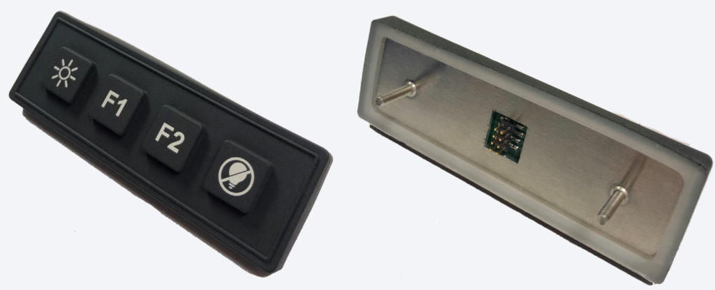
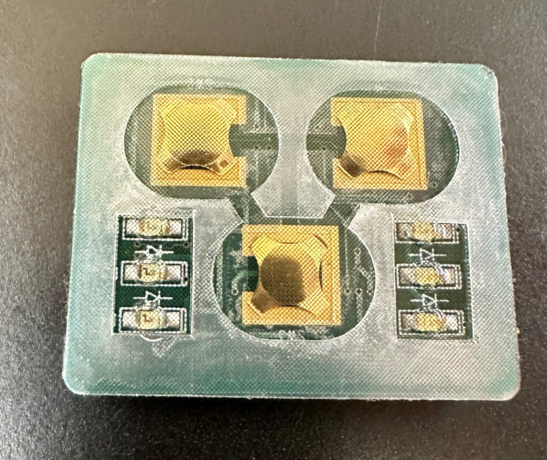
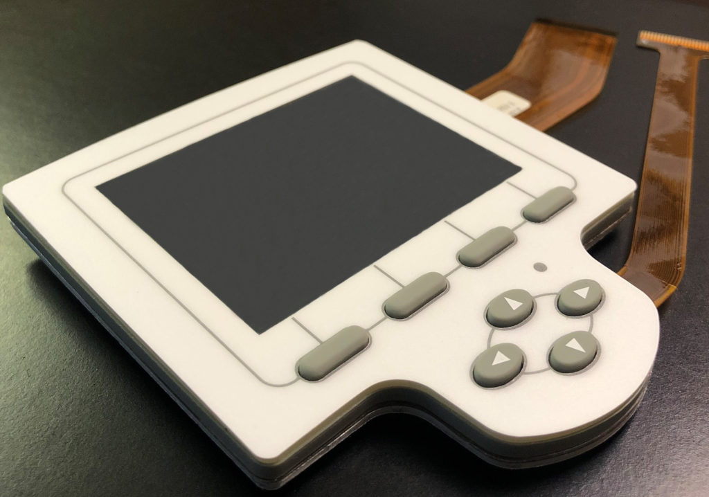
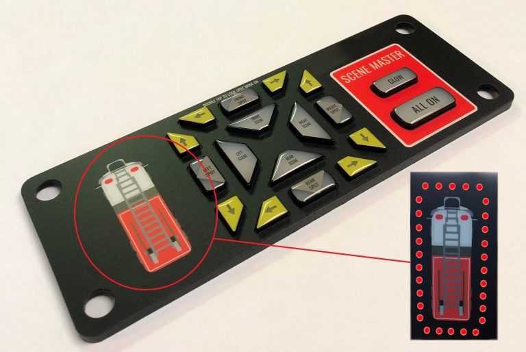
Flexible membrane keypads which incorporate surface mounted LED’s or tactile metal domes must be handled carefully and NOT flexed, bent or rolled prior or during the application process.  The metal domes and LED’s are susceptible to varying degrees of damage when flexed, etc.  If testing prior to assembly, the keypad MUST be placed on a flat surface so as not to overstress the domes.  Once the keypad is laminated to the mounting surface the domes and LED’s will not be damaged from normal use.

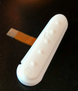
Please avoid: creasing folding the circuitry tails that exit the assembly.  A gentle radius, defined as being: no greater than if it were to be wrapped around a .100” mandrel is acceptable.  In no instance should the conductors be “hard creased” this will inevitably cause opens as it harms the circuitry.

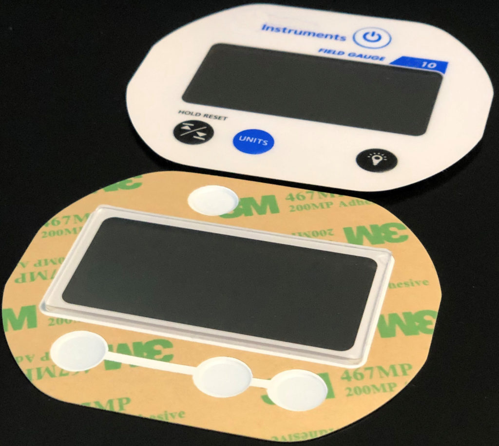
It should be noted in advance that great care is taken to protect any clear windows from scratches and blemishes.  This care needs to be continued by the customer to ensure acceptable parts.  

STEP 1 – Check your mounting surface for “bumps” or irregularities.  Surface must be clean and flat.  A tack cloth or lint free cloth and isopropyl alcohol are the proper tools for the cleaning process.

STEP 2 – Remove any separate release liner material that may be present in the flex tail or shield tab areas and discard.  Fold back approx. 1” of the main release liner (preferably at the tail exit side of the keypad, and not underneath any LED’s or metal domes) exposing the pressure sensitive adhesive (PSA).

  • Feed the tail through the tail(s) exit slot(s) and place the keypad flat on the mounting surface.
  • Align it within the center of the recess or to the edges of the backer plate.
  • Apply pressure to the face of the keypad above the exposed PSA.

STEP 3 – Carefully reach underneath the keypad and begin pulling the release liner away from the adhered part of the keypad.  While removing the liner with one hand, apply uniform pressure using a soft rubber roller.  The roller should be used to assure complete bonding and to prevent air entrapment.

STEP 4 – Hold the assembled keypad on a 45 degree angle and reflect light off of the front surface.  It should appear uniform, without bumps (air entrapment).

Note: If a keypad is misaligned or needs to be removed for any reason, the removal process will render the keypad unusable and should be discarded.

Please contact our customer service department if you require further assistance.

Redesigning your Existing Membrane Switch

Redesigning your Existing Membrane Switch​

Every week, we are approached by a customer that is having issues with a membrane switch or keypad designed by another manufacturer. More often than not, the membrane switch was not engineered properly when it was originally developed. Typically, the membrane switch is failing out in the field due moisture ingress and lack of sealing characteristics.

Because this is such a common occurrence, CSI has a seamless process in place for redesigning your current membrane switch without having to completely reinvent the wheel. We can work closely with your company in designing a drop-in replacement that will not require any product redesign or any changes for that matter on your end. CSI will update and upgrade all of the critical internal layers giving you the environmental sealing required while leaving the external layers untouched – leaving you with a completely sealed product upgrade that can be smoothly incorporated into your existing production line.

So what you waiting for?! If you are unhappy with your current membrane switch, now is the time to make the change. Reach out to CSI today to get the ball rolling and eliminate these headaches once and for all!

Integrating Windows in Membrane Switches

Integrating Windows in Membrane Switches​

Graphic Overlays with Display Windows

It is very common for our membrane switches to be applied above a display.  When this is the case, our graphic overlays can be designed and manufactured with a transparent or translucent window for viewing the display from the front of the panel. The window design is typically contingent on the type of display being used in order to maximize the visibility and readability of the display.

LCD displays require clear windows therefore typically utilize windows with minimal filters with a gloss finish. Anti-glare can also be used if required. LED segment displays require less clarity and typically utilize windows with optical filtering to maintain readability in brighter settings. VFDs usually accept a matte finish.

Graphic overlays with windows are typically manufactured using the following:

    • Gloss
    • Hard-coat
    • Scratch-resistant polyester
    • Polycarbonate

The first surface (or top surface) is typically selectively textured leaving the windows glossy while offering a secondary matte surface finish. 

Windows can also be smoked and printed color dyes can be added to produce red, green, yellow, etc. to produce filters or tints.

Additionally, the LCD windows can be manufactured with alternative gloss levels for anti-glare if the membrane switch is used outdoors in a bright environment.

Optically bonded windows can also be integrated into the window design which adds thickness and durability to the window to make up air gaps between the display and window to prevent window damage.

Opti Bonded Membrane Switch

What are the Internal Layers of Membrane Switches?

What are the Internal Layers of a Membrane Switch?​

We all know about the graphic overlay layer which is the top surface of the keypad that always gets the most attention (and rightfully so).  But what’s going on behind the scenes in the sub-assembly of the membrane switch?  Let’s find out.

Dome Retainer Layer

The dome retainer layer is somewhat self explanatory. The primary function of this layer is hold the metal domes in place and position. It is typically manufactured from polyester film material.

Spacer Layer

The spacer layer is used to created a break in contact between the two conductors of the switch. This allows the switch to have its open position. The spacer design typically includes vents or channels to prevent air entrapment in the layers when the keys are pressed or actuated.

Circuit Layer

The circuit layer is the electrical aspect of a membrane switch where the conductive traces are applied using one of the two main methods of application: screen printing and photochemical etching.

  • Screen Printing or Printed Silver Circuitry: Silver conductive ink is flooded on the stencil placed above a substrate (typically polyester film).
  • Photochemical Etching or Copper Flex Circuitry: Copper laminated substrate is selectively created through photolithography and a chemical etching process.

CSI Develops Backlit Pendant Switch for Agricultural Application

CSI Develops Pendant Switch for Agricultural Application

Product: Agricultural Product

Case: Customer approached CSI requiring a backlit and sealed pendant keypad solution that would be able to withstand heavy usage outdoors with many of its users wearing gloves.

CSI Final Solution:

    • Rubber keypad with 8 dome switches
    • Keypad backlit using LEDs and rubber with laser etched symbols
    • Printed circuit board based assembly with dome switches, LEDs, and rear mounted connector
    • Rubber designed and manufactured to wrap around PCB in order to completely seal the keypad’s circuitry
    • Rear foam adhesive for mounting to customer’s case

CSI Engineers & Manufactures HMI for Handheld Medical Device

CSI Engineers & Manufactures HMI for Handheld Medical Device


Product: Handheld Medical Device

Case: Customer partnered with CSI to design and manufacture two keypads that would be integrated into a handheld medical device. Major requirements included tactile feel requirement, sealing and durability.

CSI Final Solution:

  • Molded rubber keypad assembly for the Control Button
  • Copper flex circuit
  • 5 keys with light force domes as the primary users of the product are elderly
  • Rubber keypad assembly is mounted to a custom plastic backer plate for rigidity
  • Circuit has a tail prepped for a ZIF connection in the main product’s printed circuit board assembly
  • CSI also designed and manufactured the Power Button which is also a molded silicone rubber keypad that mounts into the plastic enclosure/case and actuates a mechanical switch on the main product’s printed circuit board assembly

CSI Develops UI for Emergency Vehicle Lighting

CSI Develops UI for Emergency Vehicle Lighting

Product: Emergency Vehicle

Case: Customer contracted with CSI to design and manufacture a user interface that would be mounted inside of an emergency vehicle. Major requirements included backlighting, sealing and durability.

CSI Final Solution:

  • Molded rubber keypad
  • Epoxy coated key caps
  • Backlit keys
  • LED indicators depicting which lights on the vehicle are in use
  • Printed circuit board based assembly with dome switches, LEDs, components, thru-holes for mounting to dashboard

CSI Develops Toggle Switch for Agricultural Application

CSI Develops Toggle Switch for Agricultural Application

Product: Agricultural Vehicle

Case: Customer approached CSI requiring a backlit and sealed toggle keypad solution that would be able to withstand heavy usage.

CSI Final Solution:

  • CSI patented toggle switch design
  • Rubber base with laser etched symbols for backlighting
  • Printed circuit board based assembly with dome switches, LEDs, and rear mounted connector
  • Rear adhesive for mounting to customer’s case