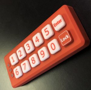
Fluorosilicone Rubber Keypads
One of the most frequently asked questions we receive regarding rubber keypads: Is there a rubber keypad material that is oil and fuel resistant? You’ve come to the right place, because we have extensive experience utilizing fluorosilicone material for such applications.
Fluorosilicone rubber is similar to silicone rubber but with fluorine properties. Similar to silicone, fluorosilcone is a stable and extremely durable elastomer that resists compression across temperature extremes. But unlike silicone, fluorosilicone contains trifluoropropyl groups that enhance its chemical resistance to non-polar solvents, fuels, oils, acids, and alkaline chemicals.
Fluorosilicone Advantages:
1. Oil, fuel, solvent and chemically resistant.
2. Heat and cold resistant.
3. Can be decorated using specially formulated inks and treatment agents.
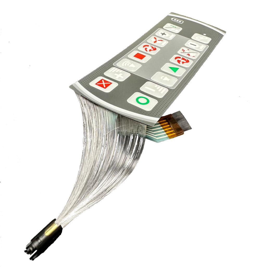
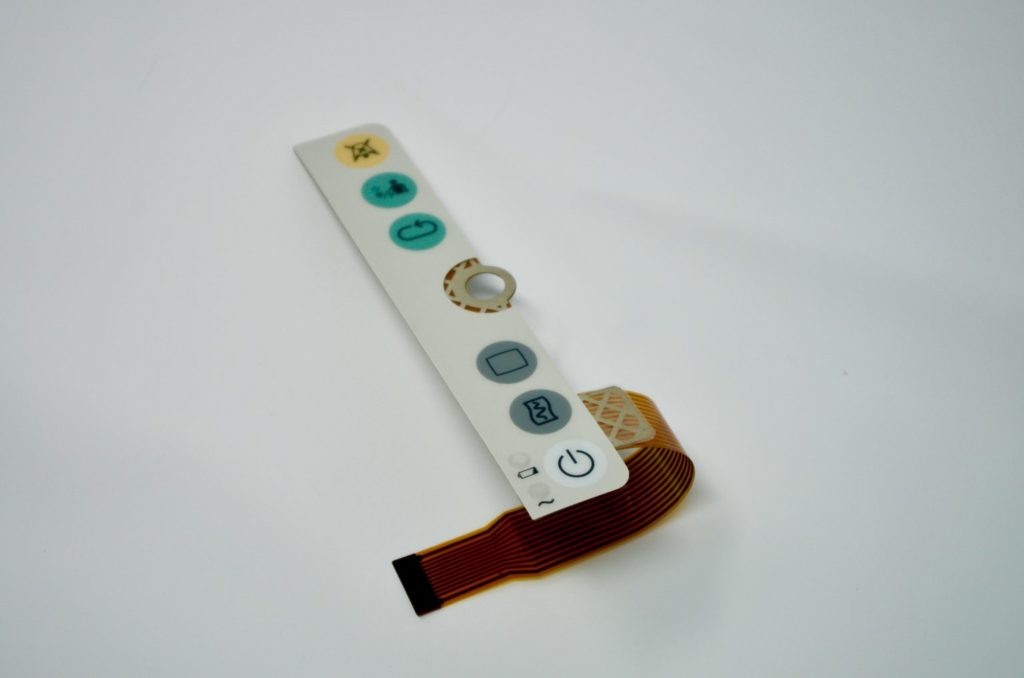
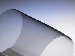
Backlighting membrane switches with fiber optics provides many benefits that cannot be obtained using standard LED backlighting or EL techniques.
Advantages:
1. Fiber optics provides a flexible and customizable back lighting layer (as thin as 0.2 mm) that can easily be incorporated between the graphic overlay and the circuit layer.
2. Can evenly backlight the entire surface area of the membrane switch.
3. Fiber optics allow for a uniform and evenly distributed backlit surface.
4. Low power consumption typically only using one single LED.
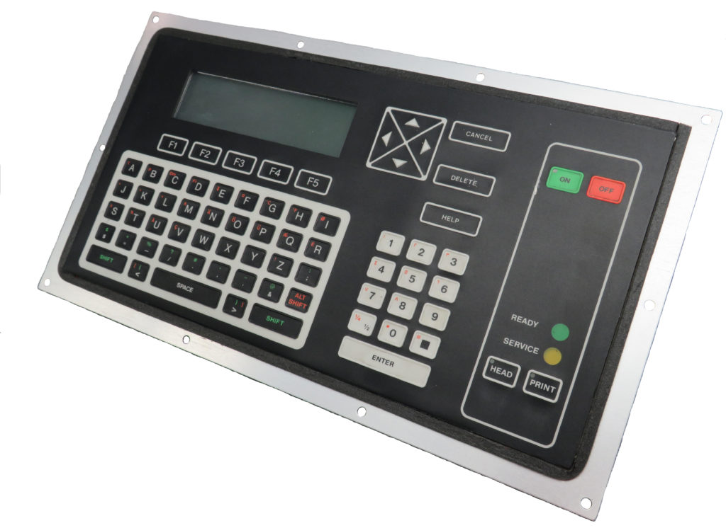
When a membrane switch is affixed to the enclosure or housing of the end product there are essentially two options: rear pressure sensitive adhesive (PSA) or a backer plate. Many of our membrane switches require backers or support layers for rigidity and structural integrity. The design often dictates whether or not a metal backer is needed. For instance, often times the customer’s enclosure or housing design requires mechanical fastening.
The most commonly used materials are aluminum or stainless steel. Other options include G10, polycarbonate or acrylic backers. Metal backers can also be supplied with a variety of hardware installed such as PEM studs.
If the keypad is PCB (printed circuit board) based, we can typically utilize the PCB as the backer and install hardware directly into the board.
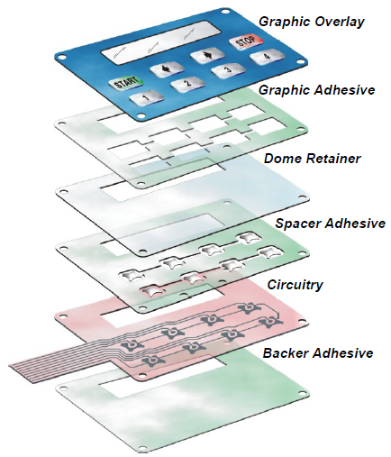
A membrane switch is an interface between man and machine, enabling an operator to communicate with equipment, instrumentation, or machinery. A membrane switch is a printed or etched electronic circuit that uses pressure to open and close a circuit. The membrane switch circuitry can be: screen printed using conductive inks which are typically made of silver or carbon, etched copper on Kapton, or can be printed circuit board based. The membrane switch overlay is typically made of polyester, polycarbonate, or molded silicone rubber. Membrane switches are part of a range of devices considered to be user interfaces or human machine interfaces (HMIs) along with touch screens and mechanical switches.
A typical membrane switch assembly typically consists of six to seven main layers:
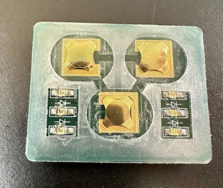
The Copper Flex Membrane Switch constructions are ideal for smaller designs, where space is at a premium, or where dense circuit patterns or trace routing limitations exist. Copper Flex membrane keypads utilize silver or copper layers which are laminated to a dielectric layer and etched away.
This switching technology combines the ability to accommodate the complex circuit patterns of a FR4 rigid printed circuit board with the flexibility of a membrane switch. Copper Flex keypads also have the advantage of being able to “hard” solder both active and passive components into the assembly, making it a good choice in high-vibration environments.
Copper Flex membrane switch panels can be produced using polyester or polyimide (Kapton) as the base material depending on your interface requirements. A very thin sheet of copper is laminated to the flexible film substrate then chemically etched away, leaving copper traces.
Copper Flex membrane switches offer you a variety of design options:
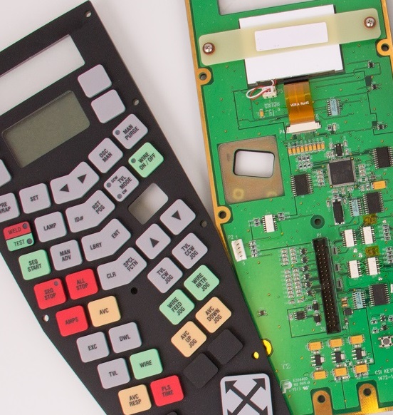
The PCB Membrane Switch construction utilizes a printed circuit board (PCB) which can serve a dual purpose in your membrane switch design. PCB Switches are typically more costly than Silver Flex membrane keypads, but can accommodate dense circuit patterns and more complex circuit patterns compared to Silver Flex membrane keypads.
A PCB membrane switch also allows the electronic components to be “hard-soldered” into the PCB, whereas membrane switch components are placed using a polymer thick film conductive paste. With a PCB membrane switch, the PCB can serve as a rigid backer, and is also a very durable and reliable method to incorporate LED’s, resistors, LCD’s and other components.
PCB membrane keyboards offer you a variety of design options:
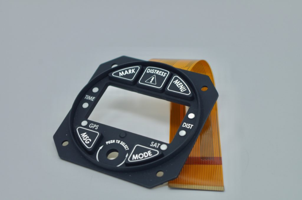
Silicone rubber keypads use compression-molded silicone rubber with conductive carbon pills or with non-conductive rubber actuators. They have exceptional resistance to extreme temperatures and aging, making them an ideal choice if reliability is a prominent concern due to likely environmental influences.
A rubber membrane switch uses compression-molded silicone rubber with conductive carbon pills or with non-conductive rubber actuators. Rubber keypads are relatively inexpensive on a per-piece basis, but require fairly expensive tooling, usually making them a design choice for higher-volume projects.
Silicone rubber keypad switches have numerous features that set this type apart from other traditional membrane switch designs. Some of the main differentiating features of this type make the silicone rubber keypad switch an ideal choice for applications requiring more durability or better resistance to exposure to moisture, chemicals, or other compounds.
Some of the primary distinctive features of silicone rubber keypad switches include:

Please provide mechanical drawings (DWG, DXF, IGES, STEP) and artwork files (AI or CDR) if available.
KEY NOTES:
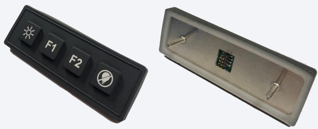
Product: Heavy Duty Military Keypad
Case: Customer approached CSI requiring an environmentally sealed keypad solution that would not only be able to withstand constant outdoor usage, but more importantly withstand exposure to mustard & sarin gas.
CSI Final Solution:

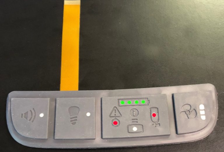
Product: Military Keypad
Case: Customer approached CSI requiring a backlit and sealed rubber keypad solution that would be able to withstand heavy usage outdoors. It was critical for the customer to be able to mechanically mount the keypad into their case.
CSI Final Solution:
Do you have a product that has stringent EMI shielding requirements? CSI can integrate EMI mesh into your keypad assembly using the finest woven blackened wire mesh. The mesh is blackened to make it suitable for optical applications such as applying over displays or under windows.
EMI protection will be provided by covering the entire keypad, display and LED conductors, etc. with wire mesh. The mesh is typically 80 x 80 density, of .0011 inch diameter stainless steel wire strands. It is an interwoven fabric, silver coated, and then blackened. The mesh shall be in direct electrical contact when attached to the enclosure. The woven mesh is highly conductive for the best EMI shielding effectiveness and is even and very black avoiding highly reflective un-blackened wires and discolorations.
Integrating the Mesh into the Design:
Flexible membrane keypads which incorporate surface mounted LED’s or tactile metal domes must be handled carefully and NOT flexed, bent or rolled prior or during the application process. The metal domes and LED’s are susceptible to varying degrees of damage when flexed, etc. If testing prior to assembly, the keypad MUST be placed on a flat surface so as not to overstress the domes. Once the keypad is laminated to the mounting surface the domes and LED’s will not be damaged from normal use.
Please avoid: creasing folding the circuitry tails that exit the assembly. A gentle radius, defined as being: no greater than if it were to be wrapped around a .100” mandrel is acceptable. In no instance should the conductors be “hard creased” this will inevitably cause opens as it harms the circuitry.
It should be noted in advance that great care is taken to protect any clear windows from scratches and blemishes. This care needs to be continued by the customer to ensure acceptable parts.
STEP 1 – Check your mounting surface for “bumps” or irregularities. Surface must be clean and flat. A tack cloth or lint free cloth and isopropyl alcohol are the proper tools for the cleaning process.
STEP 2 – Remove any separate release liner material that may be present in the flex tail or shield tab areas and discard. Fold back approx. 1” of the main release liner (preferably at the tail exit side of the keypad, and not underneath any LED’s or metal domes) exposing the pressure sensitive adhesive (PSA).
STEP 3 – Carefully reach underneath the keypad and begin pulling the release liner away from the adhered part of the keypad. While removing the liner with one hand, apply uniform pressure using a soft rubber roller. The roller should be used to assure complete bonding and to prevent air entrapment.
STEP 4 – Hold the assembled keypad on a 45 degree angle and reflect light off of the front surface. It should appear uniform, without bumps (air entrapment).
Note: If a keypad is misaligned or needs to be removed for any reason, the removal process will render the keypad unusable and should be discarded.
Please contact our customer service department if you require further assistance.