Membrane Switch Construction
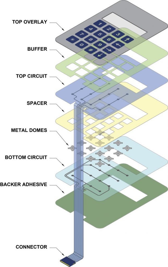
Typically a membrane switch assembly typically consists of six to seven main layers:
- Graphic Overlay – Graphic overlays are typically constructed of polyester, the material of choice due to its superior chemical resistance and flex life compared to polycarbonate. CSI can either digitally print, screen-print, or employ a combination of both methods to insure you get the right colors, textures, and finishes your Silver Flex membrane switch design requires.
- Overlay Adhesive – The overlay adhesive layer bonds the graphic overlay to the top circuit layer. This overlay adhesive is typically an acrylic adhesive, selected for its durability and ability to maintain adherence in atypical environments, such as moist environments.
- Top Circuit Layer – Typically a .005″ – .007″ heat-stabilized, polyester printed layer with silver-filled, electrically conductive inks and dielectric inks. This layer can also encapsulate metal domes or incorporate polydomes, which are used to achieve tactile feedback, an important design consideration impacting usability.
- Circuit Spacer – This layer separates the top circuit from the bottom circuit, so the switch remains normally open until the keypad is pressed. The circuit spacer is a polyester spacer with adhesive on both sides.
- Bottom Circuit Layer – The lower circuit layer is typically a .005″ – .007″ heat-stabilized, polyester-printed layer with silver-filled electrically conductive inks and dielectric inks. This layer terminates as a flexible tail that serves as the interconnect to controller PCB’s or other electronics.
- Rear Adhesive Layer – This adhesive layer bonds the entire membrane switch package to the product enclosure, housing, or to a rigid support panel. CSI can specify the appropriate adhesive type and thickness to bond your membrane keypad to your equipment.
- Rigid Support Layer – This optional layer can add structural integrity to the membrane switch assembly. Materials can be aluminum, FR-4, steel, etc. Mounting hardware such as studs and standoffs can also be utilized in this layer.