Front Panel Assembly and Turnkey HMI Solutions
CSI Keyboards has over 35 years of experience specializing in the integration of the below technologies into complex user interface turnkey keypad assemblies which has made us the one stop shop for all HMI turnkey interface solutions and front panel input interface assemblies and modules that incorporate electronic components. Our broad product line and engineering expertise allows for us to design and manufacture fully integrated interface solutions at a lower cost and better flexibility for the customer. Customers all over the world rely on CSI Keyboards’ expertise to design, manufacture, and assemble the whole turnkey user interface.
Why turn to CSI to design and manufacture your front panel?
By providing the entire value-added assembly, CSI not only minimizes the amount of moving parts for our customers but also overall time and cost. It also allows our customers the ability to place one single purchase order under one single part number for the entire front panel interface. Our longstanding supplier relationships and over 35 years of manufacturing and assembly expertise provides increased control and lower costs for your company.
From membrane keypads and elastomer rubber assemblies, to touch screens and touch panels integrated with displays, CSI Keyboards specializes in designing and fully integrating a variety of components and customized parts into a complete custom turnkey keypad assembly and user interface for your company. We can take your concepts and bring your product to fruition providing you with the complete plug and play keypad package from one dependable and experienced source.
Features of an HMI Assembly
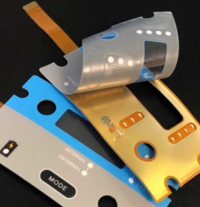
Value-Added Membrane Switch Panel and Turnkey User Interface
Fully Loaded PCBs (printed circuit boards)
Integrated Touch Screens
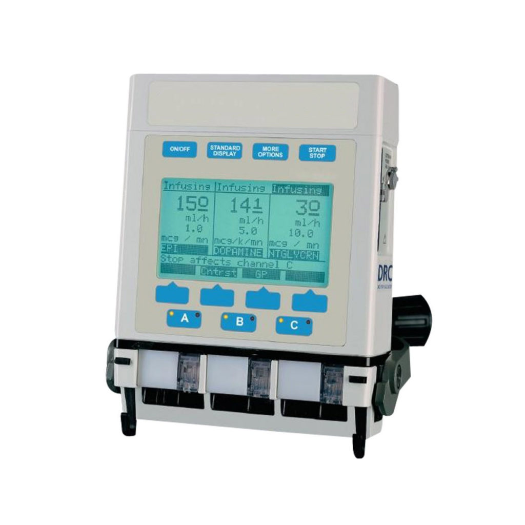
Integrated Displays
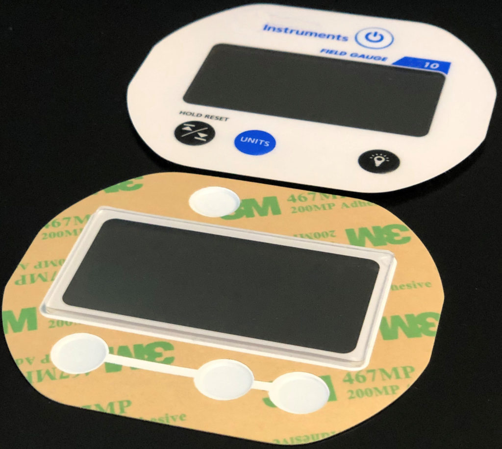
Integrated Display Windows
Optical bonding and adhesive bonding for touch screen + display solutions
G10 Backers
Metal Backers
Flexible Circuits
Enclosures and Housings
Bezel Integration and Assembly
Connectors
Cable Assemblies
EMI / ESD / RFI Shielding
Barcode scanners
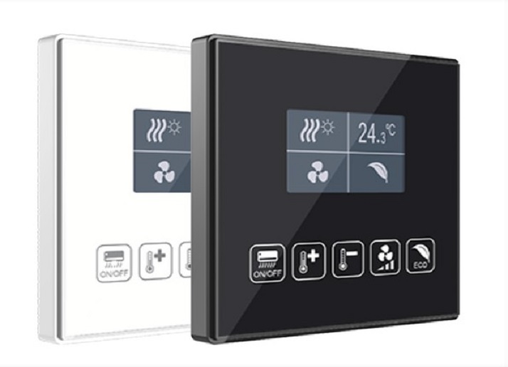
Integrated Touch Screen and Display Solutions
CSI Keyboards’ Integrated Touch Screen and Display Solutions are second to none, combining our many technologies and utilizing our interface expertise to meet your specific product requirements. CSI is able to provide a full all in one, turnkey touch screen assembly incorporating the touch panel, display, and controller integrated into a bezel, open-framed design, panel mount, or keypad. Using optical bonding or adhesive bonding, CSI Keyboards can provide a fully integrated touch screen + display solution to meet your medical requirements. Our touch screen solutions can then be integrated with a graphic overlay, membrane keypad, rubber switch, or bezel for a complete value added assembly. CSI interfaces are carefully designed and built to survive in any environment. Our touch screen solutions can be sealed to prevent moisture and contaminant ingress and are designed to withstand repeated use and chemical cleaning. Applications include medical, POS, industrial, kiosks, military, retail, gaming, office automation, transportation, and commercial.