Preventing Membrane Switch Failures

Preventing Membrane Switch Failures

A lot of time and effort go into designing and manufacturing membrane switches, so it can be such a shame if the final product is not properly handled or assembled upon completion. Typically, the number one cause of keypad failures is in fact improper handling or assembly. 

Here are a few quick prevention tips to help you avoid damaging your membrane switches:

1. Key Pressing: Do not press the domes or keys in the air or unsupported as this will result in dome damage (such as bent domes). If a key feels “dead” or “flat”, it’s usually due to a bent and damaged dome. Ensure the membrane switch is on a flat and rigid surface when pressing any of the keys. 

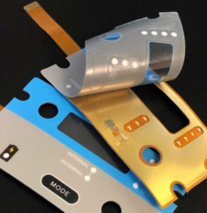
2. Bending or Flexing: Never bend or overly flex a membrane switch. Bending the switch can damage critical components on the circuit such as domes, LEDs, etc.

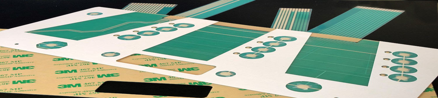
3. Creasing Circuit Tails: Avoid creasing a printed silver circuit tail. The creasing of a silver flexible circuit will most assuredly cause the silver ink to crack. Copper flex circuity is more forgiving and allows for creasing, more on that here.

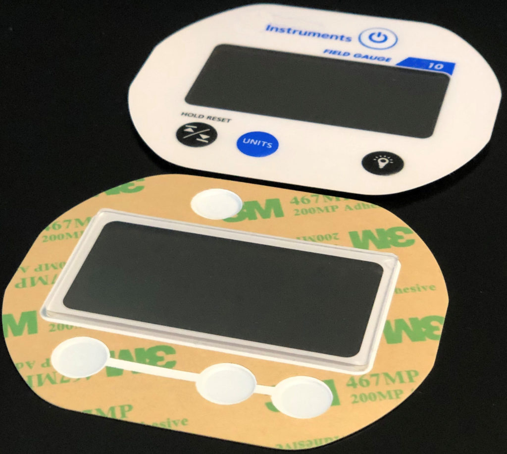
4. Keypad Surface: Ensure that the surface (the keypad is being applied to) is clean and debris-free prior to membrane switch application. It’s always great assembly practice to clean the surface with isopopyl alcohol prior to adhering the membrane switch to your assembly.

Membrane Switch Copper Flex Circuitry

What Are Discrete LEDs and How Are They Utilized?

What Are Discrete LEDs and How Are They Utilized?

Discrete LEDs are surface mounted LEDs that are typically either lit individually or together to illuminate a small area. They are ideal for lighting small icons and indicators. They are popular in many user interface designs due to their low cost and thin construction.

However, there are situations when discrete LEDs are not suitable for an application or design. The biggest issue is that they can create hotspots (bright areas) over or near the LED. As a result, they aren’t ideal when lighting larger areas because the backlighting is often inconsistent with some areas brighter than others. 

There are a couple of ways to avoid hotspots in your design. The first way is through the use of an elastomeric or silicone rubber faceplate overlay (versus polyester/polycarbonate). Elastomer is a great conductor of light and therefore allow for excellent light dispersion across a large area using discrete LEDs. 

If you prefer to use a polyester or polycarbonate overlay, CSI could also utilize side firing LEDs and light guide film to backlight a larger area. Other options are fiber optic technologies, or EL panels.

How are Membrane Switches and HMIs Tested?

How are Membrane Switches and HMIs Tested?

Testing the membrane switches or HMIs after they are assembled and before they ship is a critical step in our process. CSI Keyboards’ in-house testing capabilities are some of the most comprehensive in the user interface industry. We have custom design testing programs that are programmed to your specifications, saving valuable time in the development process while maintaining product quality and consistency.

Custom Electrical Circuit Testing

To ensure proper functionality of printed electronics, CSI  has developed custom electrical circuit testers. The testers can be used to measure and test membrane switches, printed circuit and other printed electronics. Every key, LED, and component of the membrane switch is tested before it is carefully packaged and shipped out the door. CSI offers circuit testing on 100% of our printed electronics components. 

Vision System Testing

CSI Keyboards is equipped with a variety of custom design vision systems for part inspection. The systems utilize specialized vision tools for measurement and visual defect inspection, which enables CSI to ensure the conformity of various manufactured parts.

CSI utilizes in-house tools and machinery for mechanical coordinate measuring to take precise and exact measurements. Measurements are checked carefully to ensure parts are built per specifications. 

Optical Bonding in Membrane Switches and User Interfaces

Optical Bonding in Membrane Switches and User Interfaces

The type of bonding technology you choose for your membrane switch or HMI are all dependent on the design and product requirements. There are three typical bonding methodologies: liquid optically clear adhesive (LOCA), optically clear adhesive (OCA), and air gap bonding. CSI will work closely with you in the early stages of the product development to offer a custom designed solution to fit your exact requirements. 

Opti Bonded Membrane Switch

Bonding Options:

Liquid Optically Clear Adhesive (LOCA)

The air gap between the display surface and the rear side of the sensor is filled with a UV liquid adhesive. The adhesive is silicone-free, non-aging and UV stable. The method is typically suitable for TFT displays with frames.

The liquid adhesive is applied over the cover glass and then bonded to the touch panel or TFT panel. The adhesive is spread evenly and bubble-free between the two components. The adhesive is cured without heat using UV light. This prevents.

LOCA offers the most robust and best overall performance of any bonding technology.  Handheld devices such as tablets and laptops have led the way using LOCA in display integration. Other industries such as agriculture, military and avionics have incorporated LOCA because of its durability. 

Optically Clear Adhesive (OCA)

This is a lamination process with optically clear adhesive (OCA). A lamination from “soft to hard” takes place, e.g. a film-based sensor (ITO / mesh) behind the cover-lense. With the help of storage in an autoclave, the air bubbles are eliminated.

OCA is commonly used on touchscreens, LCD flat panel displays, transparent graphic overlays and other devices requiring an optically clear bond.  OCA’s thin, consistent thickness makes it an ideal choice for flexible to rigid bonding and tight tolerance bonding situations.  OCA is classified as a dry film, pressure sensitive adhesive and there are different versions depending on the application and substrate to which it will be applied.

Air Gap

In this process, the display is glued with an adhesive frame directly behind the sensor or on the printing of the cover-lense in a clean room. An air gap between the display and the sensor and cover-lense remains. Air bonding is both a simple and cost-effective way to integrate displays with cover-lenses or touch sensors. Depending on the application, the assembly takes place with single adhesive strips or with a closed adhesive frame. Both economical and lightweight, an air gap display construction is a popular option for personal handheld electronics such as smartphones. The layers are integrated with a gasket leaving behind a small air gap. 

Laser Etching and How it’s Used to Backlight Rubber Keypads

Laser Etching and How it's Used to Backlight Rubber Keypads

When a rubber keypad or rubber membrane switch calls for backlighting, you may often hear the term “laser etching” being used. Laser etching refers to a process in which a high powered laser is utilized to remove a layer or layers of paint on a keypad. 

A standard rubber keypad is simply printed to add graphics or nomenclature. This method will suffice as long as the keypad is not backlit. It’s a cheap and easy way to create letters, numbers, and special characters on keys, making it the preferred choice among many companies. But in order to backlight molded rubber, the rubber must be laser etched: which is a newer, more advanced method for producing backlit nomenclature, graphics, indicators, etc.

The molded rubber typically starts off as a translucent, milky-like color and is then painted with opaque colors designed into the part. The rubber is then laser etched down to the translucent layer(s) of the keypad that will eventually be backlit with LEDs. The laser is carefully guided across the surface of the key, burning away paint in select areas. After the paint has been removed, it reveals the translucent layer below. The result is a contrasting translucent and opaque color, making the backlit areas pop with a higher level of crispness, brightness and visibility.

Laser etched keypads are extremely rugged and durable. The combination of molded light blocks inside the part and the laser etched nomenclature on the faceplate make for an unmatched backlit keypad.

What is a Capacitive Switch?

What is a Capacitive Switch?

As touch screen solutions have become more prevalent especially with the use of smartphones, capacitive switches have also become a very popular interface solution. A capacitive switch is a type of touch controlled electrical switch that operates by measuring change in capacitance. It works in the same way as a smartphone with a capacitive touch screen. Essentially, a small electrical charge is transferred from your body to the switch when the surface is touched, which  causes a change in capacitance. The switch detects the change in capacitance and responds with the appropriate command.

Upon touching a capacitive switch, this electrical charge disturbs the switch’s own electrical charge; thus, causing a change in capacitance. Because of this change, the switch can identify when and where the touch occurred.

Capacitive Switch Construction:

A capacitive switch consists of three main layers, the graphic overlay, the circuit, and the backer:

  • The overlay consists of the graphic artwork and can also include windows, embossing, coatings, adhesives, and selective texturing.
  • The circuit switch will either be a Flexible Printed Circuit or a Printed Circuit Board.
  • The backer is the final part of the capacitive switch, and may or may not include an adhesive that must bond to your specific substrate. The most common materials used for overlays are plastic, acrylic, and glass due to their durability and versatility. 
 

Benefits of Using Capacitive Switches:

  • Easy to clean
  • Backlighting capabilities
  • Highly decorative solutions
  • Cost effective
  • Integration of displays

How to Protect a Membrane Switch from UV Exposure

How to Protect a Membrane Switch from UV Exposure

Membrane switches intended for outdoor use are most susceptible to fading from sun exposure. Being constantly exposed to the sun’s ultraviolet (UV) rays will eventually cause the outer graphic overlay layer to fade over time. In many cases, the keys will eventually become transparent or otherwise difficult to see preventing users from being able to distinguish between the different keys.

An outdoor weatherable hardcoat material is essential when designing a membrane keypad that is used outdoors. The Uweatherable material utilizes a coating technology that resists yellowing and hazing, no matter how bright the sun is. Along with good UV resistance, this material also has chemical and abrasion resistance. This material is the perfect choice for outdoor keypad applications.

Additional Key Benefits of the UV Weatherable Material:

  • Extreme durability
  • Printable
  • Abrasion resistance
  • Chemical resistance to strong household cleaners and industrial chemicals

What is a Keyboard Matrix in a Membrane Switch?

What is a Keyboard Matrix in a Membrane Switch?

A keyboard matrix circuit is a type of keyboard that has a grid-like array of horizontal and vertical wires connecting the key switches. If the keyboard features 8 rows and 8 columns of wires, for instance, it can support up to 64 keys. The switches are located at the intersection of these wires. Keyboard matrix circuits contain a scanner or sensor that monitors these wires and is constantly scanning the grid determining which key has been pressed. The main advantage of using a matrix circuit design is the reduction of required wires. 

The matrix arrangement allows for current to flow backwards through part of the circuit, which can lead to phantom keys. Keyboard matrix circuits usually require diodes at the intersections of the wires to prevent phantom keys. Phantom keys, also known as “ghost keys” occur when the keyboard thinks that a key is pressed when it is actually not pressed at all. The diodes are typically placed in series with each switch (before or after).

How are Membrane Switches Constructed?

How Are Membrane Switches Constructed?

Membrane Switch Construction

A typical membrane switch assembly typically consists of six to seven main layers:

1. Graphic/Interface Layer – The graphic or interface layer is typically constructed of polyester, the material of choice due to its superior chemical resistance and flex life compared to polycarbonate. CSI can either digitally print, screen-print, or employ a combination of both methods to insure you get the right colors, textures, and finishes your Silver Flex membrane switch design requires. The interface layer can also be molded silicone rubber which has become a very popular choice. 

2. Overlay Adhesive – The overlay adhesive layer bonds the graphic overlay to the top circuit layer. This overlay adhesive is typically an acrylic adhesive, selected for its durability and ability to maintain adherence in atypical environments, such as moist environments.
Top Circuit Layer – Typically a .005″ – .007″ heat-stabilized, polyester printed layer with silver-filled, electrically conductive inks and dielectric inks. This layer can also encapsulate metal domes or incorporate polydomes, which are used to achieve tactile feedback, an important design consideration impacting usability.

3. Circuit Spacer – This layer separates the top circuit from the bottom circuit, so the switch remains normally open until the keypad is pressed. The circuit spacer is a polyester spacer with adhesive on both sides.

4. Lower Circuit Layer – The lower circuit layer is typically a .005″ – .007″ heat-stabilized, polyester-printed layer with silver-filled electrically conductive inks and dielectric inks. This layer terminates as a flexible tail that serves as the interconnect to controller PCB’s or other electronics.

5. Rear Adhesive Layer – This adhesive layer bonds the entire membrane switch package to the product enclosure, housing, or to a rigid support panel. CSI can specify the appropriate adhesive type and thickness to bond your membrane keypad to your equipment.

6. Rigid Support Layer – This optional layer can add structural integrity to the membrane switch assembly. Materials can be aluminum, FR-4, steel, etc. Mounting hardware such as studs and standoffs can also be utilized in this layer.

What is the Difference Between Flexible Circuit and PCB Based Membrane Switches?

What is the Difference Between Flexible Circuit and PCB Based Membrane Switches?

When designing a membrane switch, one of the most critical aspects that must be decided early-on in the design stage is the circuit type. The whole design and construction of the part is based around the type of circuitry that is used. The three types of circuitry options are: silver flexible circuits, copper flex circuits, or printed circuit board (PCB). If you are unsure as to what circuit is best for your application, CSI can work closely with you in proposing which option is ideal for the design.

Silver Flexible Membrane Switches

Silver Flex membrane switch panels utilize screen-printed silver and carbon conductive inks printed on flexible polyester layers separated by an adhesive spacer. This is the most common design used in flexible, custom membrane keypads, offering a slim, space-saving design.

Silver Flexible circuity is also more cost-effective when compared to electromechanical switch assemblies and the process of screen-printing conductive silver inks onto a flexible, film substrate poses less potential threat to the environment compared to chemically etched copper.

Silver Flex membrane switches offer you a variety of design options: 

  • Tactile and non-tactile with either metal or polyester tactile domes
  • Embedded LED’s
  • Fiber Optic backlighting
  • EL (Electroluminescent) backlighting
  • Rigid backers such as aluminum and FR4
  • EMI/RFI shielding
  • Standard connectors on .100″ centers, or prepared for ZIF connections
 

Additionally, a Silver Flex membrane switch uses a graphic overlay, which also has a number of design options:

  • Digital printing, screen-printing, or a combination of both
  • Pillow or rim embossing
  • Transparent and/or tinted display windows
  • Selective textures
  • UV hard-coat surface finishes
Copper Flex Membrane Switches

The Copper Flex Membrane Switch constructions are ideal for smaller designs, where space is at a premium, or where dense circuit patterns or trace routing limitations exist. Copper Flex membrane keypads utilize silver or copper layers which are laminated to a dielectric layer and etched away.

This switching technology combines the ability to accommodate the complex circuit patterns of a FR4 rigid printed circuit board with the flexibility of a membrane switch. Copper Flex keypads also have the advantage of being able to “hard” solder both active and passive components into the assembly, making it a good choice in high-vibration environments.

Copper Flex membrane switch panels can be produced using polyester or polyimide (Kapton) as the base material depending on your interface requirements. A very thin sheet of copper is laminated to the flexible film substrate then chemically etched away, leaving copper traces. 

Copper Flex membrane switches offer you a variety of design options:

  • Single and double sided designs
  • Lower electrical resistance and higher conductivity vs. traditional Silver Flex membrane switches
  • Tight trace routing capabilities
  • Thin profile and flexibility of Silver Flex membrane switch
  • Plating options can be tin-lead, nickel, or gold
  • Tactile and non-tactile with either metal or polyester tactile domes
  • LED’s and other components can be soldered

PCB Based Membrane Switches

The PCB Membrane Switch construction utilizes a printed circuit board (PCB) which can serve a dual purpose in your membrane switch design. PCB Switches are typically more costly than Silver Flex membrane keypads, but can accommodate dense circuit patterns and more complex circuit patterns compared to Silver Flex membrane keypads.

A PCB membrane switch also allows the electronic components to be “hard-soldered” into the PCB, whereas membrane switch components are placed using a polymer thick film conductive paste. With a PCB membrane switch, the PCB can serve as a rigid backer, and is also a very durable and reliable method to incorporate LED’s, resistors, LCD’s and other components.

PCB membrane keyboards offer you a variety of design options:

  • Tactile and non-tactile with either metal or polyester tactile domes
  • Pillow or rim-embossed graphic overlays
  • Embedded LED’s that are soldered directly into the PCB
  • Fiber Optic backlighting
  • EL – (Electroluminescent backlighting)
  • Rigid backers such as aluminum and FR4
  • EMI/RFI shielding
  • Unlimited choice of connectors, which can be soldered directly into the PCB