What is Embossing in Membrane Switches?
To provide tactile feel to a membrane switch or graphic overlay, the polyester or polycarbonate material can be embossed to raise the key area. Embossing is achieved by raising the key area using magnesium membrane switch overlay embossing dies. Embossing has really become standard in membrane switch designs. Not only does it give it a better look and feel, but it also allows the user of the end product to find the key with ease and provide tactile confirmation that the button is present even before it’s pressed.
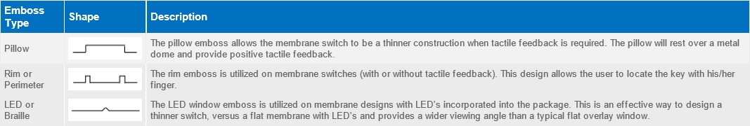
There are essentially three options when it comes to embossing membrane switches:
1. Pillow emboss
2. Rim or perimeter emboss
3. LED or Braille emboss
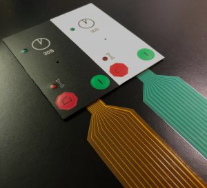
A common issue that many membrane switch manufacturers have when backlighting keypads are hot spots. A hot spot occurs when the light source used for backlighting doesn’t evenly distribute the light causing some areas to appear brighter (hot spot), while other areas are dimly lit.
CSI Keyboards is a global leader in membrane switch backlighting and interface backlighting technology. Whether backlighting a logo, individual keys, or the entire interface surface, CSI will design and manufacture a backlit membrane keypad switches or backlit interface that will stand out both visually and aesthetically. Backlighting on a membrane switch can be a simple and cost effective solution to enhance the user experience.
Evenly lighting a large area with a small light source like an LED can be challenging. The main challenges are the size of the backlit area, the amount of LED’s that can fit in the area, and the proximity of the LED’s to the backlit feature. Backlighting a small icon can be relatively easy, but the larger the backlit area, the more difficult it will be to evenly light the graphic without the appearance of hot spots. This is especially true if there is not enough room to place multiple LED’s surrounding the backlit feature.
How to Avoid Hot Spots
CSI Keyboards is an expert and integrating Light Guide Film (LGF) into our backlit solutions to prevent hot spots from occurring. Light Guide Film is designed to evenly distribute light from top or side firing LEDs, providing bright, uniformed illumination. It also reduces the amount of LEDs needed, saving power consumption. More on light guide film technology below. The design and utilization of light guide film technology has become one of the most common methods of interface backlighting. CSI Keyboards uses proprietary techniques to design the light guide film so it is optimized for light redirection and reflection giving the customer the brightest possible backlighting solution. Light guide film dots are also designed and implemented which allow for the optimization of light distribution to obtain maximum brightness and uniformity. Common problems that many of our competitors face are light leakage and hot spots. CSI’s backlighting designs prevent any light leakage and hot spots from occurring, and also result in much brighter light guide film and interface.
It’s always important to remember that the earlier CSI is involved in the design process the better. It’s a lot more difficult completely redesigning the backlighting layout, versus ensuring it is right from the onset of the design process!
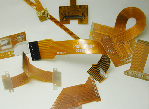
The connector on a membrane switch assembly is one of the most critical aspects of the machine interface as the connector attaches the membrane keypad to the product it will control. Without the connection working correctly the membrane switch is essentially useless. Connectors consist of contacts and a molded plastic housing.
The standard for membrane switch connectors has always been the female type receptacle with a plastic housing, typically on .100” centers. This system is simple but extremely reliable. The housings can also be equipped with a latching/locking mechanism which can serve as a polarization feature, but more importantly, can provide a connection that will not slip or vibrate loose during extreme conditions. The receptacle can come with a tin plating or a gold plating.
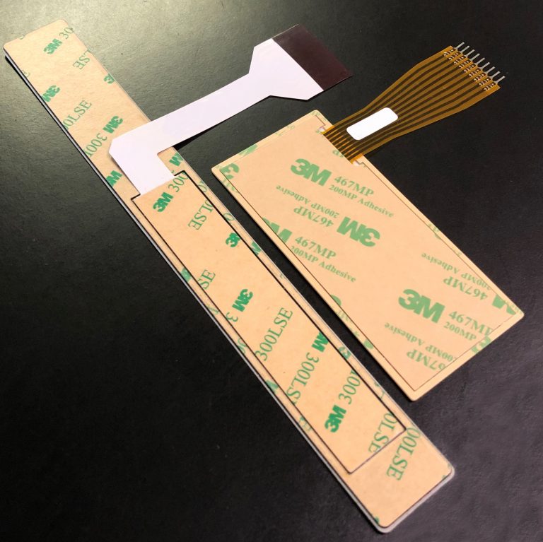
As membrane switches continue to get smaller and smaller in design, the 1mm center ZIF (zero insertion force) style connection system is becoming more and more popular. With a ZIF connector membrane switch design, the interface does not have a connector assembled to the flexible tail. Instead, the tail design is designed to slide and lock into a connector on the user’s printed circuit board. A stiffener is laminated under the tail to ensure stability and maintenance of the electrical contact. Tails are also constructed with conductive silver tracks that are then over-printed with carbon. The carbon provides a good protective cover over the silver and also battles the phenomenon of silver migration. ZIF connectors may have anywhere from 2 to 30 positions on a single row, and distances of between 1mm and 2.54 mm are available. Additional information on the the types of connectors CSI typically likes to design into their membrane switch assemblies can be found on our Material Specifications page.
A typical silicone rubber keypad involves designing a flex wall around the perimeter of the button. When the key is pressed, the flex wall flexes and produces a tactile response (similar to a spring). When the key is fully pressed, the flex wall allows the center of the key to make contact with the circuit.
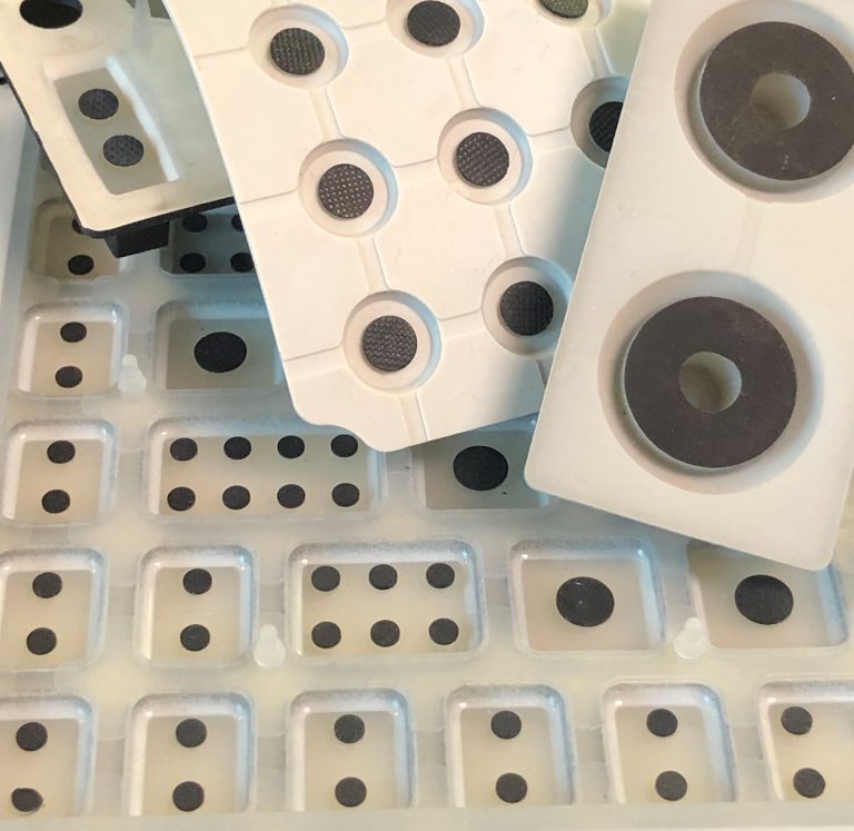
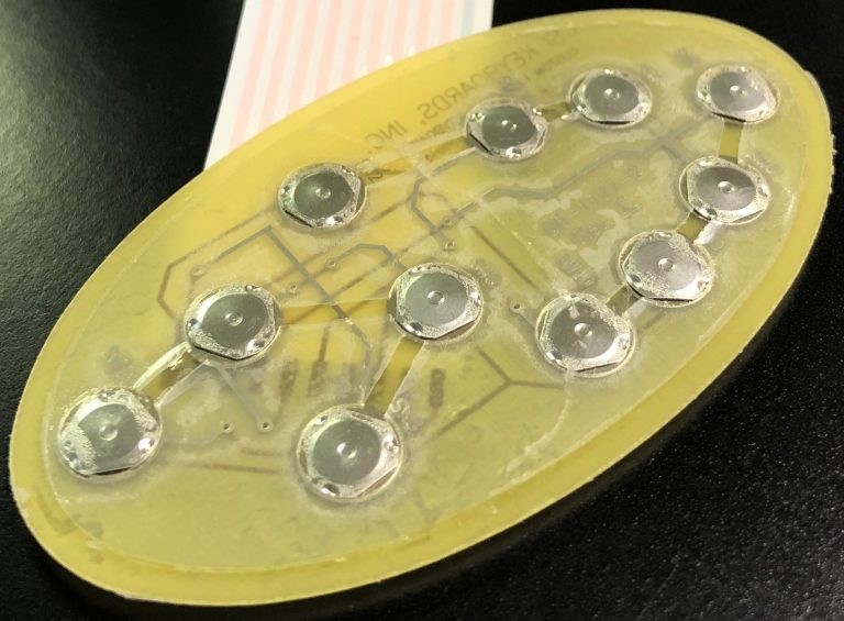
In rubber keypads, there are typically two methods of making contact with the actual switch: dome switches or conductive carbon pills. Conductive carbon pills are typically manufactured from a silicone conductive material that contains carbon. Conductive pills are molded into the actuators of the keys. When the carbon pill makes contact with the circuit, it is closing the circuit on a printed circuit board or flexible circuit trace.
Conductive carbon pills are usually silicone based and can be round, oval, or rectangular in shape. Carbon pills can range in size depending on the size of the key but typically available from 2.0mm to 8.0mm in diameter. Multiple carbon pills can also be utilized and designed into the part to ensure solid contact is made depending on the key shape, size and design of the keypad.

The Achilles heel for membrane switch sealing is most always the flex tail breakout area. The tail typically breaks out of the rear of the switch and because the tail is made of the same material as the circuit, a filler piece replaces the ribbon cable shape in the materials of the membrane switch. The gaps on either side of this tail filler is typically where moisture can enter the membrane switch.
A gasket or perimeter seal frame design can solve this problem. A membrane switch with a gasket or perimeter seal does not have a tail filler therefore there is no direct pathway for liquid ingress. CSI Keyboards’ perimeter seal frame switches have proven to be as robust as other sealing methods such as perimeter temperature sealing and can be included in your design at minimal additional cost.
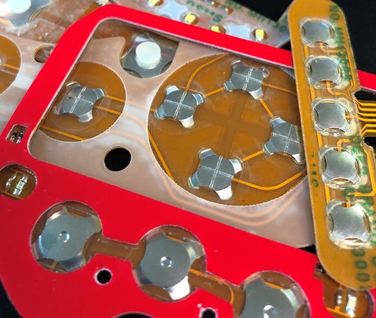
CSI Keyboards designs domes into the majority of our membrane switches. Dome switch keypads use two circuit board traces in conjunction with a metal dome. Metal domes, which are typically made of stainless steel, are momentary switch contacts that provide tactility or “snap” when pressed. The domes become normally-open tactile switches when actuated on the circuit.
The main advantage of dome switch keyboards is the tactile snap or feedback when actuated. When pressing the key, the user realizes they have actually actuated or successfully pressed the switch due to the feel and sound feedback received from the dome.
Another major benefit of the dome switches are the the long lifespan and reliability. Standard dome switch keypads are now rated from one million to even five million cycles. They are still the most reliable type of switch available in the membrane switch space.
Dome Options:
How Do I Choose the Right Dome for my Membrane Switch?
The CSI engineers will work very closely with you in deciding which dome is best for your application. Typically the decision is based on the force of the dome (how soft or hard of a press it takes to actuate the dome) and is extremely subjective. CSI can mock up different sample keypads with different dome options so the customer can decide through a more “hands-on” approach.

A non-tactile membrane switch is a switch that lacks snap or tactility when pressed or actuated. Non-tactile membrane switches are constructed of copper flex circuity using polyimide Kapton as the base material. Copper flex keypad switches are manufactured by laminating a thin sheet of copper to a flexible film substrate. The copper is then chemically etched away, leaving the copper traces. An additional layer of polyimide is laminated to the circuit leaving the gold contacts exposed.
Non-tactile membrane switches are typically designed into a product due to one of the following reasons:
LEDs:
LEDs are the most popular and economical method for keyboard backlighting. LEDs are a great option for backlighting non-tactile membrane switches, as they can be easily integrated into the flexible circuit and act as indicator lights providing visual feedback for users, since they don’t feel the snap of a switch when they pressed. LEDs are most commonly used to backlight keys, icons and symbols. LEDs are also typically used as indicator lights. A combination of LEDs, Light Guide Film and proprietary CSI backlighting methods can be designed to backlight the entire surface of a user interface.
Light Guide Film (LGF):
Light Guide Film is designed to evenly distribute light from top or side firing LEDs, providing bright, uniformed illumination. It also reduces the amount of LEDs needed, saving power consumption. More on light guide film technology below. The design and utilization of light guide film (LGF) technology has become one of the most common methods of interface backlighting. CSI Keyboards uses proprietary techniques to design the light guide film so it is optimized for light redirection and reflection giving the customer the brightest possible backlighting solution. Light guide film dots are also designed and implemented which allow for the optimization of light distribution to obtain maximum brightness and uniformity. Common problems that many of our competitors face are light leakage and hot spots. CSI’s backlighting designs prevent any light leakage and hot spots from occurring, and also result in much brighter light guide film and interface.
Electroluminescence (EL):
EL is applied on a very thin layer between the graphic overlay and the circuit. EL uses a printable ink deposit to illuminate the switch and provide a uniformed illumination.
Fiber Optics:
Fiber Optics provide a flexible back lighting layer that can be incorporated between the graphic overlay and the circuit layer allowing the entire surface area of the membrane switch to be evenly backlit.
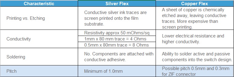
CSI Keyboards uses copper flex circuitry in the majority of our custom keypad designs due to its excellent dielectric strength, thermal stability, chemical resistance and flexibility. Copper flex, also known as Kapton circuits, have become the superior choice over printed silver especially for outdoor applications.
A printed silver circuit can be replaced with a copper and polyimide construction with minimal additional cost. Copper flex circuitry construction designs offer a significant advantage over printed silver.
Copper Flex membrane switch panels are produced using polyimide (Kapton) as the base material. Copper flex keypad switches are manufactured by laminating a thin sheet of copper to a flexible film substrate. The copper is then chemically etched away, leaving the copper traces. An additional layer of polyimide is laminated to the circuit leaving the gold contacts exposed.
The biggest case against using printed silver circuitry and thus using copper flex circuity is a phenomenon known as silver migration which occurs in microelectronics, components, PCB assemblies and membrane switches. Silver migration is the ionic movement of silver between two adjacent traces that inevitably results in a temporary electrical short.
Silver is a very active metal and is thus highly susceptible to silver migration or dendrite growth. Yet it is also a very cost effective metal for the electronic industry because of it’s conductively and usability. With the reduction or elimination of lead in electronics, silver is a very attractive choice because of its solderability and conductivity.
Silver Migration with Membrane Switches
Silver migration in membrane switches was a much bigger problem in the 1970’s and 1980’s; mainly because of the technical inability of the membrane switch manufacturers. In some cases these manufacturers were graphic screen printers who could screen print silver paste, but had little understanding of electronics or reliability issues associated with the electronics industry.
Today, with competent membrane switch manufacturers, silver migration is less of a problem. However, there are situations such as severe environments or design constraint issues where silver migration is still a risk. As in all aspects of electronics, the industry drive to reduce space and reduce costs with increased functionality continually pushes the envelope for designers and manufacturers of membrane switches.
Causes of Silver Migration
Two factors are typically required to create silver migration in a circuit using silver as the conductor:
1) A voltage potential between two traces.
2) The presence of moisture.
Ways to Reduce or Prevent Silver Migration
Some or all of the following solutions can be used to reduce or prevent the occurrence of silver migration.