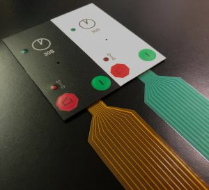
When a Non-Tactile Membrane Switch Makes Sense
A non-tactile membrane switch is a switch that lacks snap or tactility when pressed or actuated. Non-tactile membrane switches are constructed of copper flex circuity using polyimide Kapton as the base material. Copper flex keypad switches are manufactured by laminating a thin sheet of copper to a flexible film substrate. The copper is then chemically etched away, leaving the copper traces. An additional layer of polyimide is laminated to the circuit leaving the gold contacts exposed.
Non-tactile membrane switches are typically designed into a product due to one of the following reasons:
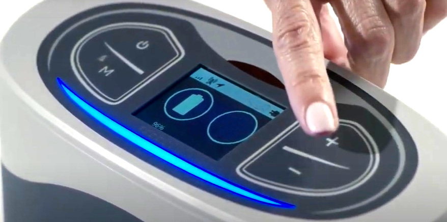
- The Need for Dense Traces to Create a Sensor or Slider Interface: typically in user interface designs where the customer is looking for a sensor or slider interface solution, where the user can run his/her finger along the surface and make contact/actuation. CSI can integrate added points, ribs, or sections providing tactile feedback. The advantage of this product is that it does not require any sensor electronics, and has no moving parts. The solution is extremely robust and cost effective. It’s a great alternative to more expensive and sophisticated capacitive touch solutions.
- Size Constraints: when there simply just isn’t enough room for domes due to the small size of the design.
- Light Activation Force: the customer wants to simply be able to run their finger over the key with a very light press in order to make contact ie does not want any snap when pressing the key.
Advantages of Copper Flex Membrane Switches
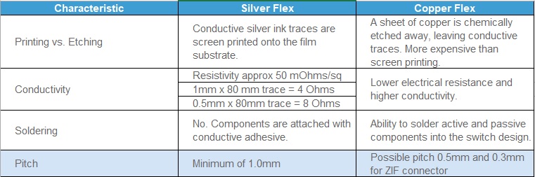
- Improved creasability – the ability to fold or crease without causing open circuits which you are susceptible to using silver ink
- Ability to put solder components directly on flex, better adhesion than bonding to silver ink
- Much more resistant to thermal shock
- No potential problems with silver migration
- Greater conductivity
- Lowering the closed loop resistance and switch bounce will be reduced by gold plating the contacts. We will have a gold to gold contact with no bounce versus silver to gold dome
- Applying stiffener to tail end using heat lamination versus cold lamination which provides better adhesion and better for pinning
- Ability to have a 0.5mm pitch vs. the 1.0mm minimum with printed silver
- Tighter trace routing capabilities
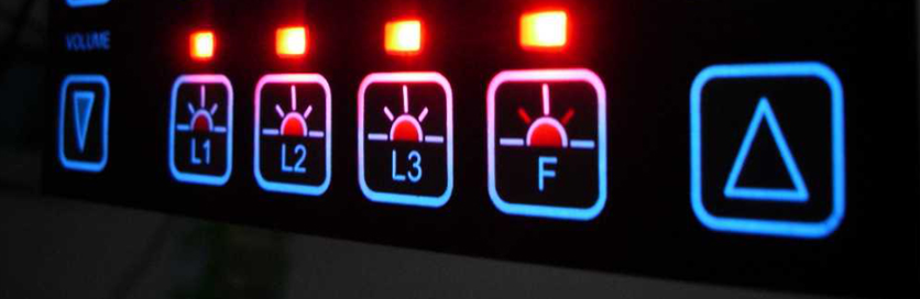
Backlighting Copper Flex Membrane Switches
LEDs:
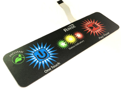
LEDs are the most popular and economical method for keyboard backlighting. LEDs are a great option for backlighting non-tactile membrane switches, as they can be easily integrated into the flexible circuit and act as indicator lights providing visual feedback for users, since they don’t feel the snap of a switch when they pressed. LEDs are most commonly used to backlight keys, icons and symbols. LEDs are also typically used as indicator lights. A combination of LEDs, Light Guide Film and proprietary CSI backlighting methods can be designed to backlight the entire surface of a user interface.
Light Guide Film (LGF):
Light Guide Film is designed to evenly distribute light from top or side firing LEDs, providing bright, uniformed illumination. It also reduces the amount of LEDs needed, saving power consumption. More on light guide film technology below. The design and utilization of light guide film (LGF) technology has become one of the most common methods of interface backlighting. CSI Keyboards uses proprietary techniques to design the light guide film so it is optimized for light redirection and reflection giving the customer the brightest possible backlighting solution. Light guide film dots are also designed and implemented which allow for the optimization of light distribution to obtain maximum brightness and uniformity. Common problems that many of our competitors face are light leakage and hot spots. CSI’s backlighting designs prevent any light leakage and hot spots from occurring, and also result in much brighter light guide film and interface.
Electroluminescence (EL):
EL is applied on a very thin layer between the graphic overlay and the circuit. EL uses a printable ink deposit to illuminate the switch and provide a uniformed illumination.
Fiber Optics:
Fiber Optics provide a flexible back lighting layer that can be incorporated between the graphic overlay and the circuit layer allowing the entire surface area of the membrane switch to be evenly backlit.