Common Membrane Switch Terminology

Common Membrane Switch Terminology

ACTUATION FORCE

The pressure required for actuating the circuit of a membrane switch or rubber keypad.

ADHESION

The strength of the molecular attraction bond of one material to another determined by the surface energy in each material.
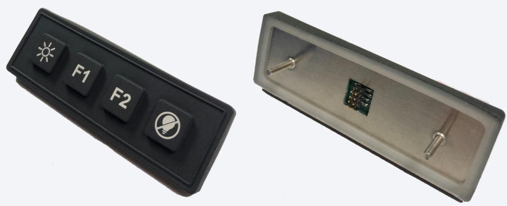
BACKERS

Incorporating backers into membrane switch assemblies for mounting or rigidity purposes. The most commonly used material is aluminum which can be supplied with a variety of hardware installed. Other backer options include G10, stainless steel, polycarbonate or acrylic materials.
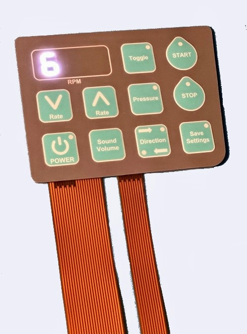
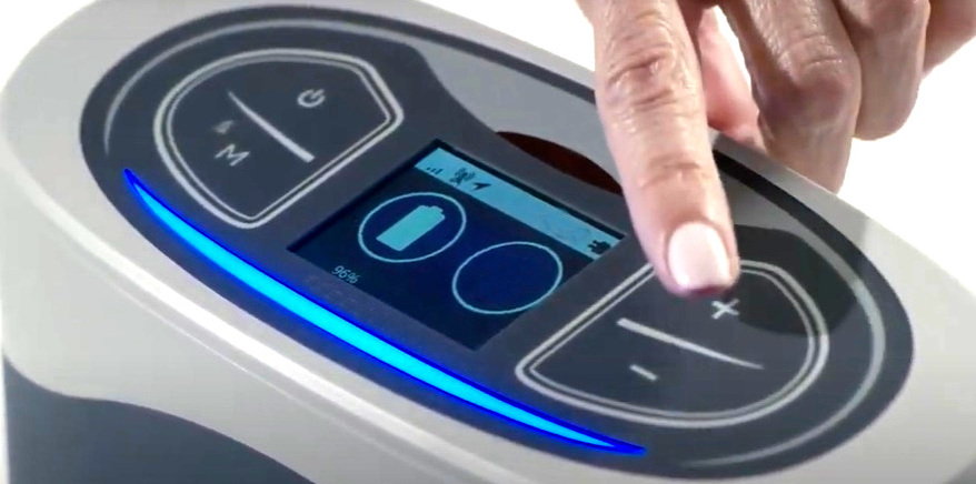
BACKLIGHTING

Lighting of membrane switches using LEDs, light guide film, fiber optics or EL panels.

BREAKDOWN VOLTAGE

The minimum voltage at which the insulation between two conductors begins to fail.

CARBON OVERCOAT

Ink that consists of prepared suspensions of carbon black and is applied over silver circuitry to mitigate the possibility of silver migration. Typically used on the flex tail contacts which is the area on the flex circuit most susceptible to silver migration.

CIRCUITRY

Electrical circuit used to operate a membrane switch typically either printed silver, copper flex or printed circuit board based.

CONDUCTIVITY

A material’s ability to allow the flow of electrons.
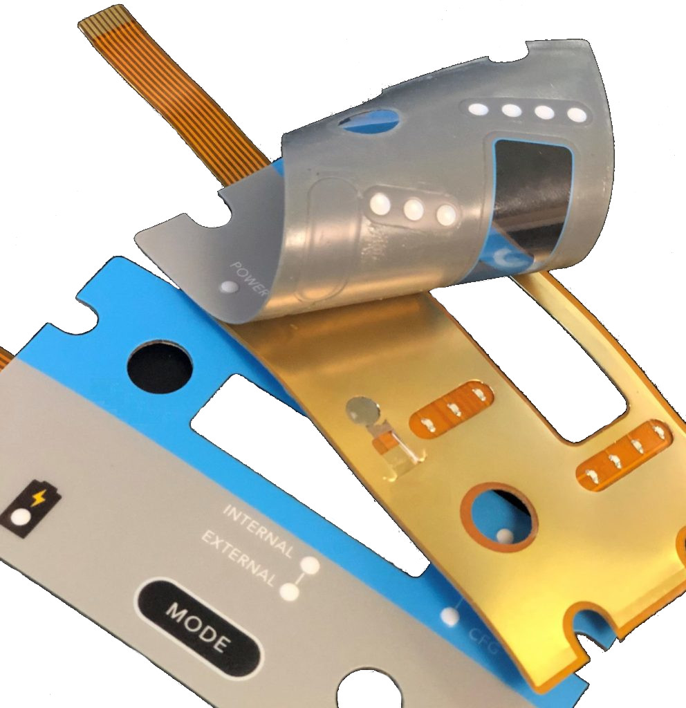
COPPER FLEX

A type of circuitry used in membrane switches produced using polyimide (Kapton) as the base material. Manufactured by laminating a thin sheet of copper to a flexible film substrate, the copper is then chemically etched away, leaving the copper traces. An additional layer of polyimide is laminated to the circuit leaving the gold contacts exposed. Also known as Kapton circuits, they have become the superior choice over printed silver especially for outdoor applications due to their excellent dielectric strength, thermal stability, chemical resistance and flexibility.

CROSS-OVER

A conductor intersection where the traces are kept separated and insulated by dielectric material insulator.

DEAD FRONT

A cosmetic feature of a graphic overlay in which an artwork feature is only visible when backlit.

DIELECTRIC / DIELECTRIC INKS

An insulating or non-conducting medium. The inks are used for printing protective patterns on conductive printing to isolate selected areas from electrical contact with other conductors. Typically used for cross-overs and tail insulation.

DOMES

A tactile metal dome (or a snap dome) is a normally open momentary contact that provides a crisp tactile feel letting the user know the button was pressed/actuated. Polydomes can also be utilized if necessary.

DOME RETAINER

An adhesive layer made to hold metal domes in the key-switch.
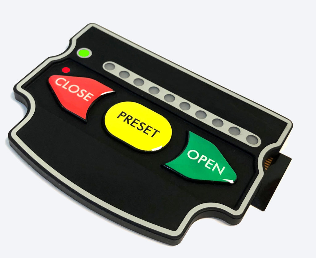
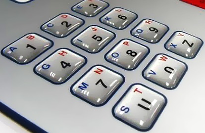
EMBOSS

Method of raising an aspect or aspects of the overlay material to accentuate key surfaces through mechanical and thermoforming of graphical features. Typically used for keys and/or LED indicators.

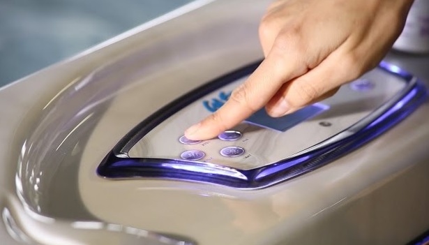
ENVIRONMENTAL SEALING

Utilizing proprietary design features in order to seal a membrane switch or rubber keypad. Such features include frame sealing, the use of copper flex circuitry and rubber gasketing.
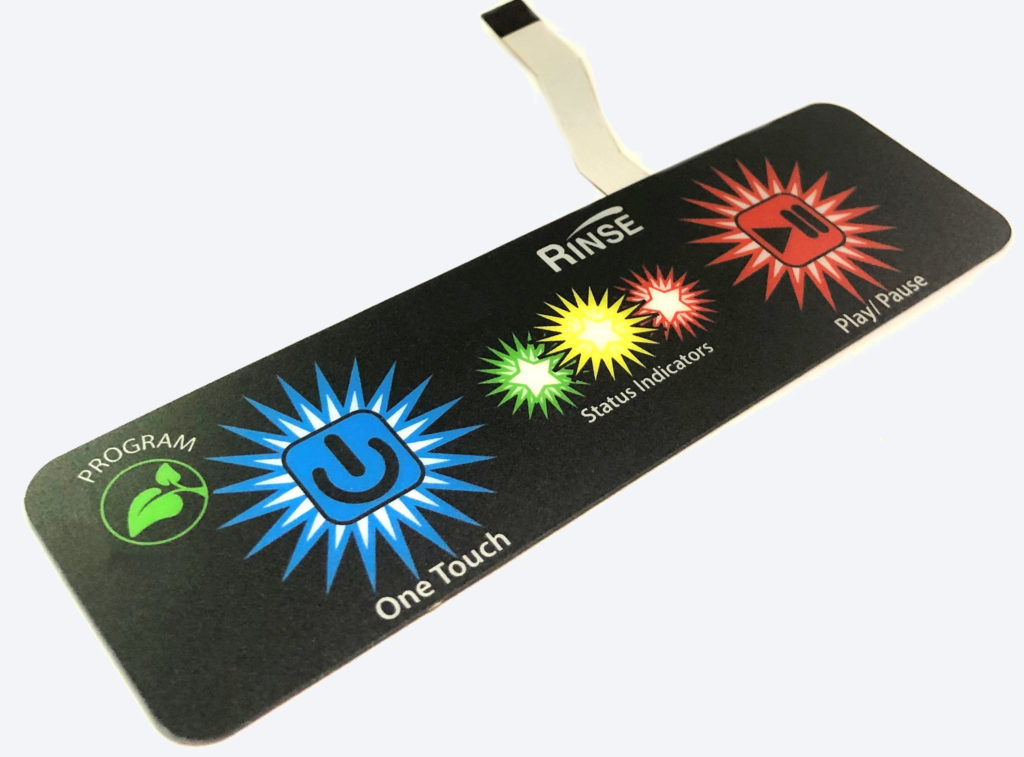
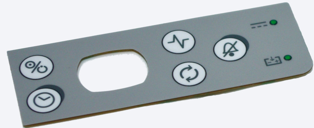
GRAPHIC OVERLAY

The decorative front layer of a membrane switch or control panel.

KEY HEIGHT

The distance from the highest point of a key to the base of the keypad.

LIGHT EMITING DIODE (LED)

Assembled to the membrane switch circuitry to illuminate a feature or features on the keypad.
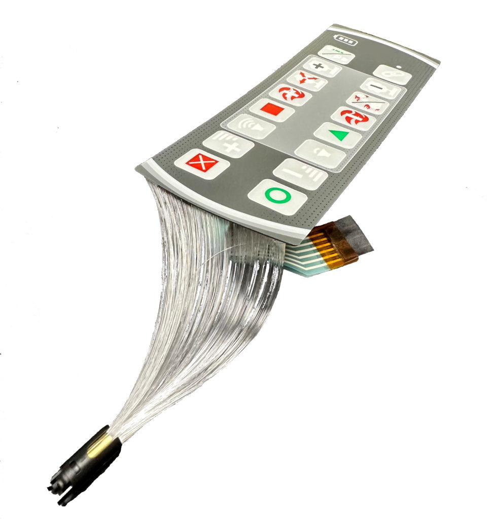
PINOUT

The schematic that describes the circuit output requirements for membrane switches. Also known as a wire diagram.

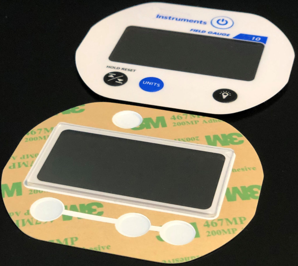
PRESSURE SENSITIVE ADHESIVE (PSA)

Adhesive materials that bond through the application of pressure without the need for heat or solvents.

REAR PSA

A pressure sensitive adhesive applied to the back of a membrane switch for mounting purposes. Different types of rear PSA can be utilized depending on the application and bonding surface.

SHIELDING

Utilizing methods for incorporating ESD/RFI/EMI shielding within the membrane switch layers.

SECOND SURFACE PRINTING

Practice of printing a graphic overlay from the bottom in reverse, so the outer layers protect the graphic.  This is particularly useful in membrane switch applications where the graphic overlay experiences abrasive wear.

SILVER INKS

Tiny particles of actual silver suspended in various substrates that produce conductive patterns on rigid and flexible substrates.

SPACER LAYER

A membrane switch adhesive layer separating the electronic circuit layers with button/switch openings.
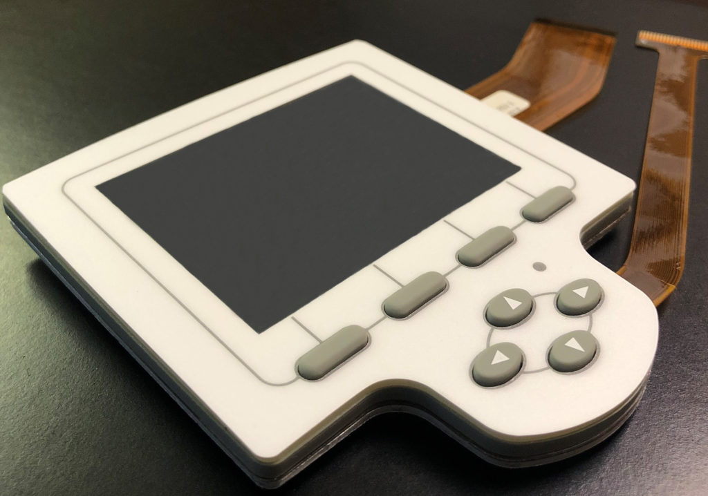
TAIL BREAKOUT

The location of the tail exit on the back of the membrane switch.

VENTING

Membrane switch openings connected to one another to seal the switch from moisture and other contaminants without venting externally. External venting is also an option if the design allows for it.

WINDOWS

Utilizing the base clear overlay to incorporate windows in a membrane switch typically for displays. Can utilize hardcoats or textures depending on the application. Incorporating a reinforced opti-bond window is also a common technique for windows susceptible to excessive abuse.

WIRE DIAGRAM

A diagram showing the desired connections to the pinout connector.

Membrane Switch Copper Flex Circuitry
Membrane Switch Copper Flex
Backlit Rubber Keypads
Membrane Switch Silver Circuit
Sealed Rubber Keypad

Emulating Seven Segment Displays in Membrane Switches

Emulating Seven Segment Displays in Your Membrane Switch or HMI

Are you looking to integrate a seven segment display or displays into your interface but are encountering space constraints and/or trying to keep costs down? 

CSI has years of experience emulating seven segment displays using LEDs, light guide film and light blocking features. We also utilize additional methods including light “piping” features within the layers of the membrane switch. We can integrate LEDs of any color and any window color to give you the exact aesthetic you are looking for in your product. The result is a thinner membrane switch package size at a much more cost effective price.

Advantages:


1. Thinner membrane switch package size.

2. More cost effective than using actual seven segment displays.

3. Can integrate into a flexible circuit (versus printed circuit board).

Of course, if you want to use actual seven segment displays that is also an option but will most likely require a printed circuit board design (versus a thinner flexible circuit) and an overall thicker membrane switch package. The CSI engineering team can assist you in this process in order to ensure you get exactly what you are seeking for your interface.

Seven Segment Displays in Membrane Switches

Most Suitable Graphic Overlay Material for UV Resistance

Most Suitable Graphic Overlay Material for UV Exposure

A very common question many customers ask us: is there a graphic overlay material that is better suited for a product that will live outside with constant UV exposure?

The answer to this question is really dependent on the membrane switch design.

If the membrane switch doesn’t have a window, then the polyester Autotex XE would be ideal.

If the membrane switch does have a window, then we have found that the best UV resistant graphic overlay material is actually polycarbonate as there is no available UV polyester (including Autotex XE) that is non-textured which would be required for any part with a window. 

When it comes to UV resistant polycarbonates, these are really the best available material options:

HP92W: UV resistant gloss hard coat – non-texturable

HP92X: UV resistant – texturable

Thicknesses:

.007 (7mil) is needed for anything that requires an emboss

.010 (10mil) can be used for parts that don’t require an emboss or standalone windows.

Hot Tub Keypad

Utilizing Epoxy Keys in Membrane Switches

Utilizing Epoxy Keys in Membrane Switches

Often times, membrane switches are simply embossed which is the process of raising the key area using magnesium membrane switch overlay embossing dies. A popular alternative to embossing the overlay material is using epoxy keys.

Epoxy keys are applied using a precise dispensing process. Epoxy keys are typically used for aesthetic purposes giving the membrane switch a clean look and really making the keys pop. Epoxy keys are still raised off of the surface allowing the user to easily locate the keys similar to an emboss.

Epoxy keys are also utilized when there are space constraints around the keys. If the keys are too close together or close to the edge of the part, there often times isn’t enough space to emboss due to adhesion issues. The epoxy keys ensure there is enough adhesion around the keys to prevent delamination.

Epoxy Keys in Membrane Switch

Backlighting Membrane Switches with Fiber Optics

Fiber Optic Backlighting in Membrane Switches

Backlighting membrane switches with fiber optics provides many benefits that cannot be obtained using standard LED backlighting or EL techniques.

Advantages:

1. Fiber optics provides a flexible and customizable back lighting layer (as thin as 0.2 mm) that can easily be incorporated between the graphic overlay and the circuit layer.

2. Can evenly backlight the entire surface area of the membrane switch.

3. Fiber optics allow for a uniform and evenly distributed backlit surface.

4. Low power consumption typically only using one single LED.


Fiber Optic Membrane Switch

CSI Develops Sealed Rubber Keypad for Military

CSI Develops Sealed Rubber Keypad for Military

Product: Military Keypad

Case: Customer approached CSI requiring a backlit and sealed rubber keypad solution that would be able to withstand heavy usage outdoors. It was critical for the customer to be able to mechanically mount the keypad into their case.

CSI Final Solution:

    • Rubber keypad with 4 dome switches
    • Keypad backlit using LEDs and rubber with laser etched symbols
    • Printed circuit board based assembly with dome switches, LEDs, and rear mounted connector
    • Rubber designed and manufactured to wrap around PCB in order to completely seal the keypad’s circuitry
    • Rear aluminum backer with threaded studs for mechanically mounting

Integrating Windows in Membrane Switches

Integrating Windows in Membrane Switches​

Graphic Overlays with Display Windows

It is very common for our membrane switches to be applied above a display.  When this is the case, our graphic overlays can be designed and manufactured with a transparent or translucent window for viewing the display from the front of the panel. The window design is typically contingent on the type of display being used in order to maximize the visibility and readability of the display.

LCD displays require clear windows therefore typically utilize windows with minimal filters with a gloss finish. Anti-glare can also be used if required. LED segment displays require less clarity and typically utilize windows with optical filtering to maintain readability in brighter settings. VFDs usually accept a matte finish.

Graphic overlays with windows are typically manufactured using the following:

    • Gloss
    • Hard-coat
    • Scratch-resistant polyester
    • Polycarbonate

The first surface (or top surface) is typically selectively textured leaving the windows glossy while offering a secondary matte surface finish. 

Windows can also be smoked and printed color dyes can be added to produce red, green, yellow, etc. to produce filters or tints.

Additionally, the LCD windows can be manufactured with alternative gloss levels for anti-glare if the membrane switch is used outdoors in a bright environment.

Optically bonded windows can also be integrated into the window design which adds thickness and durability to the window to make up air gaps between the display and window to prevent window damage.

Opti Bonded Membrane Switch

Mechanically Mounted & Fastened Keypads

Mechanically Mounted & Fastened Keypads

While the majority of keypad assemblies are simply adhered to the end product using rear pressure sensitive adhesive (PSA), in some cases the product design calls for mechanical mounting. Mechanically fastening the keypad assembly not only provides additional mounting support and rigidity, it also prevents the keypad from being removed or pried from the front (in many cases for security purposes) and allows our customers the flexibility to remove the keypad assemblies out in the field when required. 

The rubber keypad assembly shown below is used in an outdoor lockbox application and has the following design features: 

  • Mechanically fastened using 10 PEM studs that are integrated into the metal backer.
  • Backlit keys using LEDs, light guide film, light piping and laser etching technology.
  • Environmentally sealed utilizing the rubber which wraps around the entire assembly acting as a sealed gasket.
  • Tactile keys using metal domes.
  • Cable assembly with female connector soldered and sealed to the PCB for connection to customer’s PCB. 
Rubber Keypad Mounted to Outdoor Lock Box
Rubber Keypad with PEM Studs for Mounting
Rear View of Rubber Keypad with PEM Studs

Designing a Sealed & Backlit Rubber Keypad​

Designing a Sealed & Backlit Rubber Keypad​

Designing a rubber keypad that is both backlit and completely sealed may seem like a daunting task, but that’s what the experts at CSI are here for!  There are essentially two main components of the keypad assembly that must be properly designed: the rubber and the circuit. To better speak to the process, we will use the sample keypad on the right side of this post.


Rubber Decorating Process:

  1. The rubber starts off as a clear/milky translucent color (the color of the base material). The black portions of the keypad are rubber light blocks that are molded into the rubber to prevent light from bleeding into other portions of the keypad.
  2. The rubber is then sprayed translucent white.
  3. The rubber is then sprayed opaque black and then laser etched down to the translucent white material (for the power button) and hte clear base material (for the LED indicators) in the areas that are backlit.
  4. The rubber is carefully designed so that the actuators on the back of the keys press into the metal dome switches efficiently. 
  5. The rubber is also designed so that it provides a seal. Silicone is typically used for gasketing in many products, so why not utilize it’s properties for the same reasons in your keypad?!
  6. The rubber is then sprayed with a UV resistant coating that protects the keypad from ultraviolet exposure, while also providing chemical resistance. 


Additional Sealing Features:

Copper Flex Circuitry, also known as polyimide Kapton circuitry, are used in the majority of CSI Keyboards’ keypad designs due to its excellent dielectric strength, thermal stability, chemical resistance and flexibility. Copper Flex membrane switch panels are produced using polyimide (Kapton) as the base material. Copper flex switches are manufactured by laminating a thin sheet of copper to a flexible film substrate. The copper is then chemically etched away, leaving the copper traces. An additional layer of polyimide is laminated to the circuit leaving the gold contacts exposed. Copper flex has become the superior choice over printed silver especially for outdoor applications. Copper flex circuitry construction designs offer a significant advantage over printed silver and a printed silver circuit can be replaced with a copper and polyimide construction with minimal additional cost.

Seal Frame is a perimeter frame of adhesive that protects your circuitry from any moisture ingress. It have proven to be as robust as other sealing methods such as perimeter temperature sealing and can be included in your design at minimal additional cost.

PU (polyurethane) Coating was applied, which protects the printed and molded colors on the rubber keypad, and also increases the longevity of the printing and graphics. This coating ensures a longer keypad life regardless of the environment. We also utilize a proprietary coating specially formulated for marine and outdoor applications which provides added protection against UV exposure.

Rear 3M 300LSE Adhesive was utilized, which is the top of the line adhesive specially formulated to provide high bond strength to surfaces. Our adhesives are resistant to humidity, UV, water, temperature, and chemicals.

EMI/RFI and ESD Protection is obtained using a metalized Mylar shield layer. A separate tail for the shielding layer was designed to connect to the housing or another mechanical piece already grounded. Another option could have been grounding to a trace on the interface panel and then routed to a grounded plane on the motherboard to carry the static charge away from any nearby conductive components.

Dead Front Membrane Switch Integration

Dead Front Membrane Switch Integration

Looking to make your membrane switch or only portions of your membrane switch visible only when lit?  You’ve come to the right place. CSI Keyboards has been integrating dead front technology into our keypads and user interfaces for over 35 years.

CSI Keyboards manufactures dead front membrane switches and backlit overlays that deliver sleek and intuitive interfaces at a very reasonable price point. Icons and/or nomenclature stay dark/invisible to the user’s eye until the membrane switch backlighting is activated. CSI’s thin backlighting technology can be integrated inexpensively into new designs or product upgrades using various flexible or rigid graphic layer materials.

Dead front membrane switches can be created with either printed inks or by adding diffusing layers to the membrane switch itself. Successful integration of the graphic overlay with the membrane switch electronics dictates a custom membrane switch for almost all applications.

Dead front membrane switches can be produced in rich color to promote your brand or increase product aesthetics. Dead front membrane switches can be produced with almost any background color with black being the most common. You can incorporate just one LED light color or have multiple LED light colors within a single display.