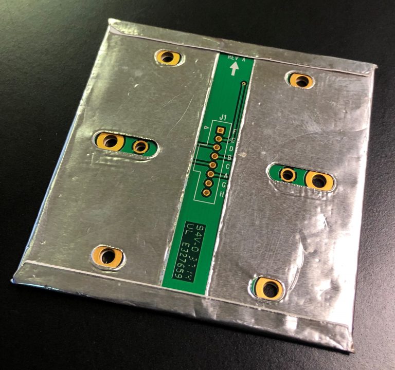
Depending on the type of membrane switch design, the graphic overlay material or the molded rubber materials both have a relatively high dielectric strength and high volume resistivity. If required, a higher degree of electrical shielding can also be integrated into the membrane switch construction. The requirements can vary depending on the industry the product will be used in.
Shields can be designed for the following:
CSI offers four shielding methods to protect membrane switches:
Shield Termination Methods:
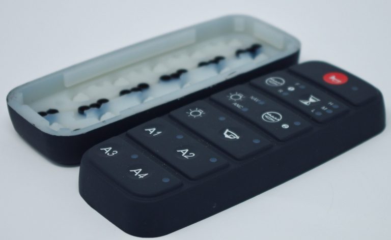
CSI Keyboards utilizes molded silicone in many of our keypad designs. Silicone is truly remarkable material. Without silicone’s properties, rubber keypads would not have moving keys, be able to close electrical switches or have self positioning features.
Part II of our Silicone Rubber Series reveals many of silicone’s basic properties that allow it to be molded into a multi-functional keypad.
Silicone Raw Material
Raw silicone starts off with the consistency of clay. The raw silicone is first mixed together with a catalyst which assists in the molding processes. Different base raw silicones are mixed together in specific ratios and formulas to achieve a very specific silicone hardness.
Silicone Hardness / Durometer
Silicone rubber keypads can be made with different hardness (also known as durometer) ranging from 30 shore A to 80 shore A durometer. Rubber bands, for instance, have a durometer of 20 shore A, plastic is about 95 Shore A or higher. Raw silicone comes in base hardness of 30, 50, 70 and 80 Shore A. The standard durometer used for a molded rubber keypad is 60 Shore.
Two raw silicones can be mixed together to achieve a specific hardness (Example: a mixture with 50% silicone at 40 Shore A and 50% at 60 Shore A will result in a final material with a Durometer of 50 Shore). The hardness or durometer is based on the purpose of the rubber such as sealing requirements, tactile force requirements, insert molded keytops, molded light blocks and pull through tabs.
Silicone Color
Without pigment, silicone has a clear but slightly milky white color. Pigments can be added to the raw silicone mixture to make parts in virtually any color. Rollers are used to integrate the pigments into the raw silicone. If a silicone rubber keypad has multiple silicone colors, each color must be prepared separately.
Matching Silicone Color
The color of the silicone rubber keypad is controlled by the amount and type of pigments used in the molding process. CSI uses the Pantone system to match silicone colors, but we can also color match parts to plastic samples or color chips. Because of silicone’s unique texture, it is possible that the keypad will not color match in certain lighting conditions. This is called metamerism. In this case, the pigment formula can be slightly changed (example: made darker or more blue). Once the color is approved, the pigment formula is locked in assuring consistent color throughout production and life of the rubber keypad product.
Transparent & Tinted Silicone
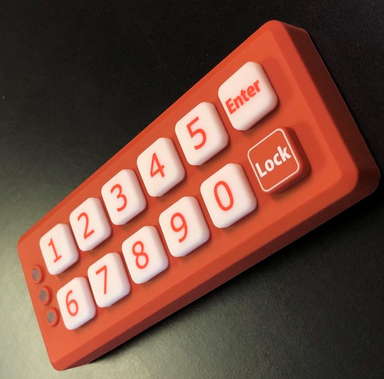
Raw silicone without pigments will appear transparent (clear) or slightly milky white after molding. This is perfect for backlighting the keypad whether backlighting indicators, nomenclature or symbols. Using a tiny amount of pigment, the silicone can be made mostly transparent with a slight color tint. By varying the pigment color and amount, the tint can also be varied from highly transparent to virtually solid.
Choosing the proper adhesive for your membrane switch is one of the more critical decisions you can make during the design process. Achieving a solid bond between your membrane switch and the surface to which it is adhered is vitally important to reducing failures and ensuring the long term reliability of your product.
Your choice of adhesive essentially comes down to identifying the appropriate family of adhesives and the proper adhesive thickness. There are two families of adhesive used for these applications: “acrylic” adhesives and “modified acrylic” adhesives.

Acrylic Adhesives
Acrylic adhesives are a popular choice, and generally considered the industry standard, for membrane switch attachment applications. They provide outstanding adhesion to metal and high surface energy plastics. These adhesives provide some initial re-positionability for placement accuracy when bonding to plastics. They also perform well after exposure to humidity and hot/cold cycles. Typical metals to which acrylic adhesives bond well to are aluminum and steel. Compatible high surface energy plastics are usually ABS, acrylic, and polycarbonate, to name a few. Acrylic adhesives offer outstanding temperature and chemical resistance, as well as excellent shear strength to resist slippage and edge lifting.
A popular acrylic adhesive choice is 3M™ High Performance Acrylic Adhesive 200MP adhesive, which offers the following performance characteristics:
Humidity Resistance: High humidity has a minimal effect on adhesive performance. Bond strength shows no significant reduction after exposure for 7 days at 90⁰F (32⁰C) and 90% relative humidity.
UV Resistance: When properly applied, membrane switches are not adversely affected by outdoor exposure.
Water Resistance: Immersion in water has no appreciable effect on the bond strength. After 100 hours at room temperature, the high bond strength is maintained.
Temperature Cycling Resistance: High bond strength is maintained after cycling four times through: 4 hours at 158⁰F (70⁰C) 4 hours at -20⁰F (-29⁰C) 4 hours at 73⁰F (22⁰C)
Chemical Resistance: When properly applied, nameplate and decorative trim parts will hold securely after exposure to numerous chemicals including oil, mild acids and alkalis.
Bond Build-up: The bond strength of 3M™ 200MP increases as a function of time and temperature
Temperature/Heat Resistance: 3M™ 200MP is usable for short periods (minutes, hours) at temperatures up to 400⁰F (204⁰C) and for intermittent longer periods (days, weeks) up to 300⁰F (149⁰C).
Lower Temperature Service Limit: The glass transition temperature for 3M™ 200MP is -31°F (-35°C). Many applications survive below this temperature (factors affecting successful applications include: materials being bonded, dwell at RT before cold exposure, and stress below the TG [i.e.expansion/contraction stresses, impact]). Optimum conditions are: bonding high surface energy materials, longer time at RT before cold exposure, and little or no stress below the TG. The lowest service temperature is -40°F (-40°C).
Benefits of 3M Membrane Switch Adhesive
3M is a leading manufacturer of membrane switch adhesives, offering a number of benefits for membrane switch design engineers and product manufacturers. From excellent moisture and solvent resistance to exceptional resistance to high temperatures and a high shear strength to withstand the ongoing stress from repeated actuation, 3M membrane switch adhesives are a viable option for a great many membrane switch applications.
3M membrane switch adhesives may also be die-cut, allowing for the use of these adhesives in applications in which selective die-cutting is necessary or desirable. These benefits coupled with UV resistance and easy application make 3M membrane switch adhesives a leading choice among membrane switch designers, although other options do exist in the market. Available in sheets, custom sizes, and rolls, there are a multitude of options to choose from depending on your design and production requirements.
Modified Acrylic Adhesives
These adhesives provide high bond strength to most surfaces, including many low surface energy plastics such as polypropylene and powder coated paints. The modified acrylic adhesives also provide excellent adhesion to surfaces contaminated lightly with oil typically used with machine parts.
An often-used modified acrylic adhesive family is 3M™ Adhesive 300LSE. Typical performance characteristics are:
Bond Build-up: The bond strength of 3M™ Adhesive 300LSE increased as a function of time and temperature, and has very high initial adhesion.
Humidity Resistance: High humidity has a minimal effect on adhesive performance. No significant reduction in bond strength is observed after exposure for 7 days at 90°F (32°C) and 90% relative humidity.
U.V. Resistance: When properly membrane switches are not adversely affected by exposure.
Water Resistance: Immersion in water has no appreciable effect on the bond strength. After 100 hours at room temperature, the high bond strength is maintained.
Temperature Cycling Resistance: High bond strength is maintained after cycling four times through: 4 hours at 158°F (70°C) 4 hours at -20°F (-29°C) 4 hours at 73°F (22°C)
Chemical Resistance: When properly applied, membrane switches will hold securely after exposure to numerous chemicals including oil, mild acids and alkalis.
Temperature Resistance: 3M™ 300LSE adhesive is usable for short periods (minutes, hours) at temperatures up to 300°F (148°C) and for intermittent longer periods of time (days, weeks) up to 200°F (93°C).
Lower Service Temperature: -40°F (-40°C).
Choosing the Proper Adhesive Thickness
Once you have determined the appropriate adhesive family for your membrane switch adhesive, it is necessary to specify the thickness of the adhesive required to achieve a successful bond of the membrane switch to the mounting surface. When bonding the membrane switch to a smooth surface, it is generally acceptable to use a 2-mil (.002″) thick adhesive. If a texture is visible on the mounting surface, a 5 mil (.005″) thick adhesive would be suggested., in order to maximize the adhesive’s ability to flow around the textured surface profile, maximizing the surface area to which the adhesive can bond.
Silicone rubber is an elastomer (rubber-like material) composed of silicone (itself a polymer) containing silicon together with carbon, hydrogen, and oxygen. Silicone rubbers have become widely used in the keypad industry, and there are multiple formulations. Part I of our Silicone Rubber Series will detail these formulations.
Silicone rubbers are often one- or two-part polymers, and may contain fillers to improve properties. Typically the silicone rubber contains properties called “Organosiloxanes Polymer” which have originated from its unique molecular structure that can carry both inorganic and organic rubbers. Due to the Si-O bond of Silicone Rubber and its inorganic properties, Silicone Rubber is superior to ordinary organic rubbers in terms of heat resistance, chemical stability, electrical insulating, abrasion resistance, weather ability and ozone resistance etc. The silicone rubber compounds are used in various ways of application such as rubber keypads, industrial rolls, wires, thermal conductive pads, medical products, kitchenware, etc.
With these unique characteristics, silicone rubber has been widely used to replace petrochemical products in various industries like aerospace, munitions industry, automobile, construction, electric and electronics, medical and food processing industry. Recently, these scopes of silicone applications have been expanding at a great speed by the high demand of industries that require a more reliable elastomer.
HTV Silicone Rubber
Silicone Rubber is classified into HTV Silicone Rubber (High Temperature Vulcanization Silicone Rubber) and RTV Silicone Rubber (Room Temperature Vulcanization Silicone Rubber) by its curing temperature. Also, HTV Silicone Rubber is divided into Millable Type Silicone Rubber and Liquid Type Silicone Rubber by its degree of polymerization.
Millable Type Silicone Rubber (High Consistency Silicone Rubber)
Millable Type Silicone Rubber is composed mainly of Polyorgarnosilioxan (Silicone Polymer) and Silica with various additives to grant diversified characteristics. We call this stage of Silicone Rubber as “Base Compound”. This “Base Compound” is catalyzed, pigmented with a roll and cured by press molding and extrusion etc. Millable Type Silicone Rubber is also typically called as “HCR (High Consistency Silicone Rubber)”.
Liquid Silicone Rubber
LSR is Liquid Type and High Temperature Vulcanization Silicone Rubber. LSR differs from Millable Type Silicone Rubber and RTV (Room Temperature Vulcanization) by its degree of viscosity and curing temperature. LSR (Liquid Silicone Rubber) is perfect rubber material for automated injection molding due to its excellent liquidity. Also, LSR (Liquid Silicone Rubber) is ideal for complex molds, demanding design and tolerance because it can easily fill the most complex part of a mold.

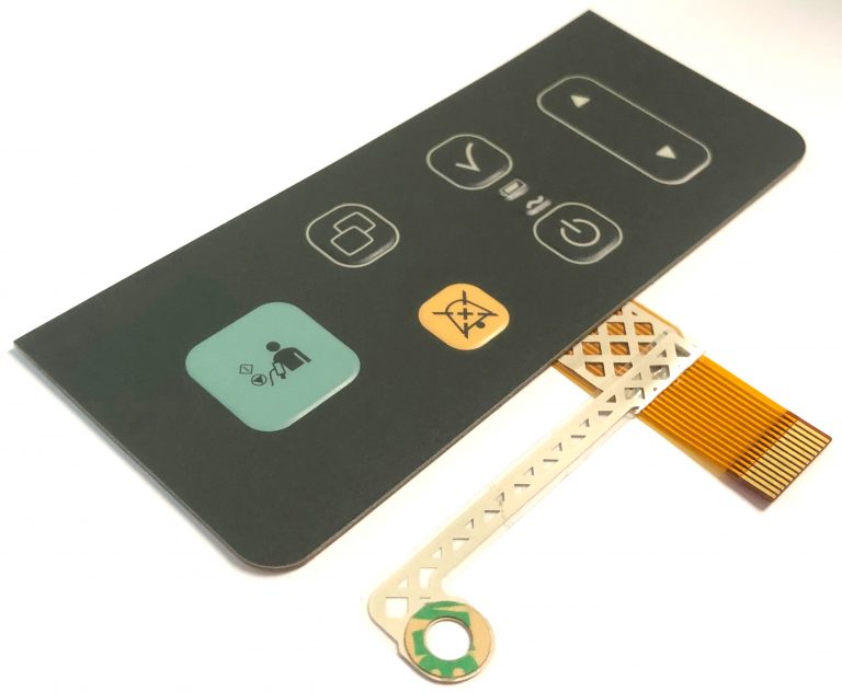
Our customers sometimes require a membrane keypad with a connection that calls for flex circuits directly connected to rigid boards versus using connectors. Connecting a flexible circuit directly to a printed circuit board requires a manufacturing procedure called hot bar solder or heat seal lamination. There are many benefits for using a direct flex-to-board connection.
The Main Benefits of Hot Bar Solder Lamination:
1. Saves vertical height in the design
2. Fast temperature ramp-up and cool-down
3. Closed loop temperature control
4. Can be more reliable than fine pitch connectors
5. Accurate positioning of the parts
6. Multiple connections can be made simultaneously
7. Cost effective due to elimination of third component such as connector
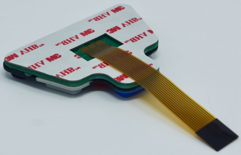
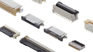
ZIF connectors have no physical connector on your membrane switch and rely on a receptacle connector that is available from numerous manufacturers. It is important to choose a ZIF connector that is suggested for membrane switches and to keep in mind that smaller pitches are available in polyimide flexible printed circuits only.
ZIF connectors are increasingly common in several applications, especially when connecting to a small display or keyboard. ZIF connectors meet a range of requirements including low profile, lightweight, secure, and removable connections. ZIF connectors are appropriate for more complex applications and allow for higher levels of integration. For ZIF connections, the connector system is not on the membrane tail, but on the PCB. The tail of the circuit is inserted into the ZIF connector to create the contact, and a stiffener is laminated under the tail to ensure stability and maintenance of the electrical contact. ZIF connectors may have anywhere from 2 to 30 positions on a single row, and distances of between 1mm and 2.54 mm are available.
Keep in mind that ZIF connections degrade with insertions, so the maximum number of insertions should not exceed 10 cycles. It’s also important to remember to take care when placing the tail die but in relation to the printed traces, since resistance in the circuit may increase in spacing of less than 1mm where the circuit traces are thinner.
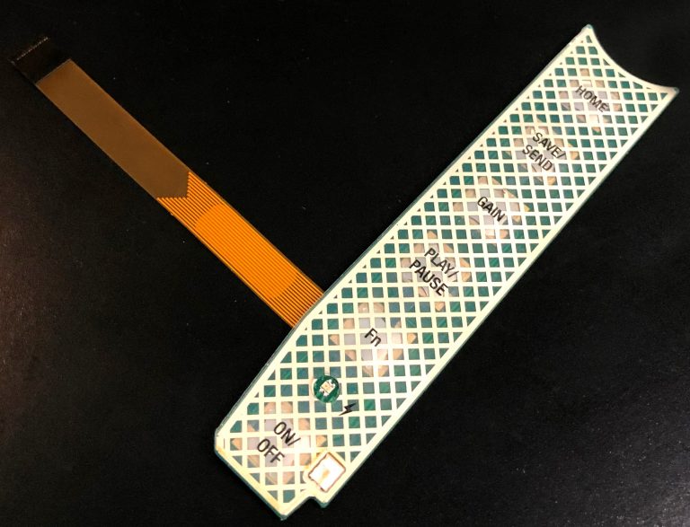
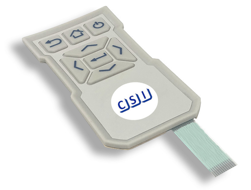
CSI Keyboards uses copper flex circuitry in the majority of our custom keypad designs due to its excellent dielectric strength, thermal stability, chemical resistance and flexibility. Copper flex, also known as Kapton circuits, have become the superior choice over printed silver especially for outdoor applications. A printed silver circuit can be replaced with a copper and polyimide construction with minimal additional cost. Copper flex circuitry construction designs offer a significant advantage over printed silver.
Below are some key flex circuit terms that you should know:
Access Hole – A series of holes in successive layers of a multilayer board, each set having their centers on the same axis. These holes provide access to the surface of the land on one of the layers of the board.
Additive Process – A process for obtaining conductive patterns by the selective deposition of conductive material on clad or unclad base material.
Annular Ring – The ring of exposed solder or copper around a through hole.
Buried Via – A plated through hole buried within internal layers of a circuit. There is no direct access to the via.
Blind Via – A plated interconnection from one layer to an adjacent layer through a fixed depth LASER drilled opening.
Cantilevered Leads – Unsupported conductors extending from an edge of a flex circuit.
Circuit – A number of electrical elements and devices that have been interconnected to perform a desired electrical function.
Coverlayer – Insulating layer usually bonded with adhesive.
Dielectric – A material with a high resistance to the flow of direct current, and which is capable of being polarized by an electrical field.
Flexible Printed Circuit – A patterned arrangement of printed circuitry and components that utilizes flexible base material with or without flexible coverlay.
Land – A portion of a conductive pattern usually used for the connection and/or attachment of components.
LCP – Liquid Crystalline Polymer, a relatively new dielectric substrate used in the manufacture of flex circuits.
Micron – A linear dimension equal to 1 x 10⁻⁶ meters or 39.4 x 10⁻⁶ inches.
Photo Etching – The chemical, or chemical and electrolytic, removal of unwanted portions of conductive or resistive material.
Phototool – A phototool is a physical film which contains the pattern that is used to produce a circuitry image on a photo-sensitive material by way of exposure to light-energy such as UV light.
Polyimide – The synthetic polymer that has more than two imide radicals in the main chain.
PTH – Plated through hole. Used as a means of creating an electrical connection from one circuit layer to another.
SMT – Surface Mount Technology
Steel Rule Die – A tool used to cut flex circuits (and other materials) from a panel.
Stiffener – A rigid or semi-rigid material that is bonded to a flex to facilitate component attachment. Typically made of polyimide or epoxy glass.
Via – A plated-through hole that is used as an interlayer connection, but in which there is no intention to insert a component lead or other reinforcing material.
Windowed Leads – Conductors that are unsupported by insulation. Typically running across a window, the pitch can be quite tight allowing high density mass termination.
ZIF (Zero Insertion Force) Termination – A style of termination that allows a flex circuit tail or tab to be inserted into a circuit board mounted connector. After insertion a mechanical actuator locks the flex in place.
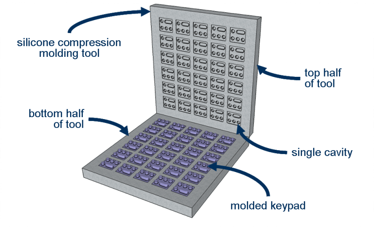
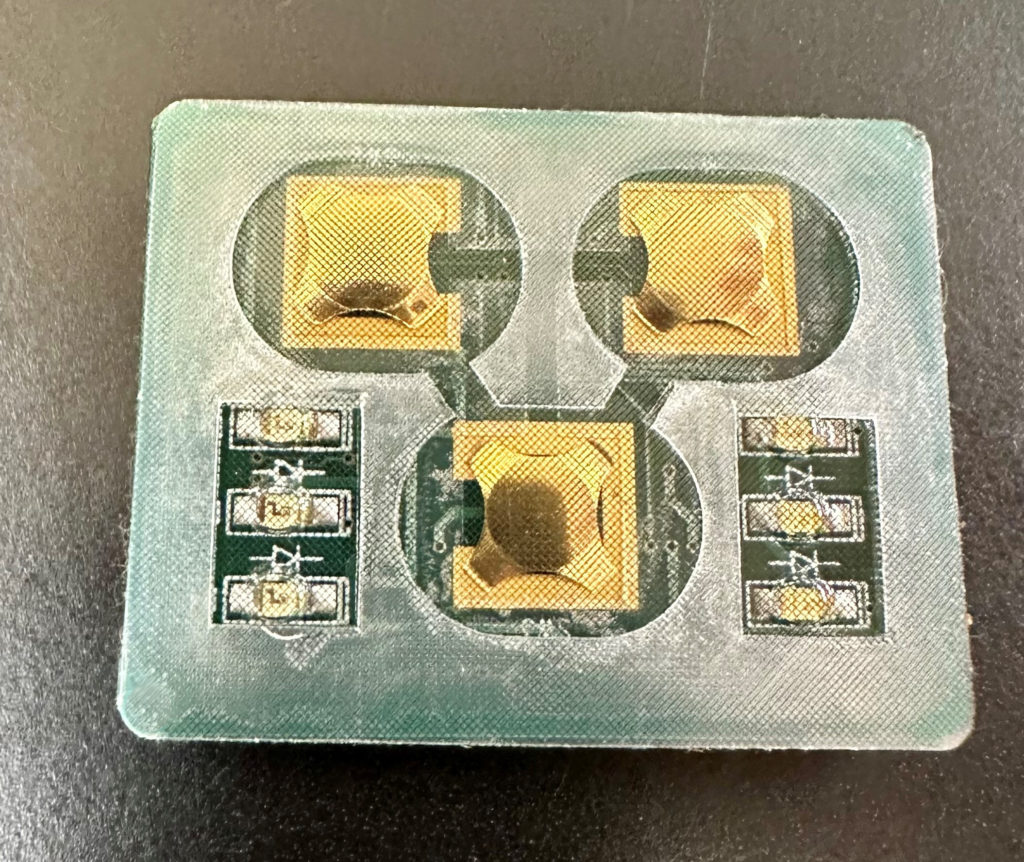
Rubber keypads are made using compression mold tooling. Compression molds have a bottom tool and a top tool (think of a waffle iron). First, the mixed raw silicone material is cut into precise cut slabs. The material is then laid into the mold set. Pressure, heat and time are used to transform the material to the shape of the cavity. The parts are removed from the tool, flash is hand torn and then the parts are post-cured to remove any residual catalyst material.
Material Set-Up
The mixed and pigmented raw silicone material must be carefully placed in the mold to ensure that enough material fills the cavity, and not too much material prevents the mold from overflowing. This is achieved by rolling the raw material to a specific thickness and width. Next an automated machine pulls and cuts the material into equal sizes. The cut pieces are weighed to ensure that their volume will correctly fill the cavity.
Vulcanization
The cut pieces are laid into a pre-heated mold, and the mold is closed. Alternative molding methods requires a different process. Typical cycle time for silicone keypads is about 5-10 minutes – which is much longer than typical plastic molding. Multiple cavities are used to increase output (having 140 cavities is not uncommon). Inside the tool, heat and time transforms the silicone mixture. First the raw silicone liquefies, filling the cavity. Next the material hardens in what is called the vulcanization process. Here the molecules of the material cross-link, permanently transforming the part into its finished shape. After vulcanization, it is not possible to revert back to the original silicone material.
Flash
Because the raw material liquifies, and must fill the entire cavity, the mold is design with overflow channels, which is why there is flash. All regions where the top of the tool meets the bottom, there will be flash. This includes the perimeter and any opening. The flash is easily removed by hand. Note that on all parts, there will always be a flash line with a small amount of silicone flash (less than 0.3mm) remaining.
Post Curing
Some residual catalyst material from the raw silicone may not have fully vulcanized and can remain in the part. Over time, this residual will leach out, depositing on the electrical contacts and potentially affecting keypad function. To prevent the post-cures keypads after they are molded. During post curing, the parts are placed in an oven to heat and evaporate any non-vulcanized catalyst.
Modifying Tools
Because of flashing, it is highly difficult to add inserts in compression tools. It is far easier to simply remove steel from the tool.For this reasons the initial design of the part must be made with careful considerations to tool modifications. Existing molds can have steel cut away (adding material to the part), but steel shouldn’t be added to the tool (remove material from the part). In the latter case, a new bottom and/or top half of the tool must typically be machined.
What is the Pantone Color Matching System?
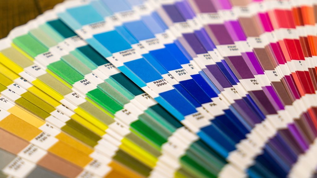
The Pantone Color Matching System or PMS is a common industry standard for color reproduction. It is regularly used in graphic overlays design, publishing, and printing companies. Instead of asking for just the color “green”, Pantone can give you the exact shade of green and allow you to communicate that red to others in a standardized, no-nonsense, uncomplicated, communicative way.
Why is the Pantone Color Matching System used?
Pantone Color Matching System is used to help clearly communicate specific and standardized colors and prevent confusion or a problem with manufacturing and printing. It allows special colors to be used and produced from metallics to fluorescents. PMS allows businesses and customers to reference and match colors no matter the media: ink or online. It allows a consistency and uniform base that will not cause a mix up in the final product.
How does PMS Work?
There are several different ways of using PMS, one of which is called the CMYK process which only uses four primary colors: cyan, magenta, yellow and black. You may recognize this as the colors that are used in your printer at home. Guidelines are used to provide the correct cyan, magenta, yellow and black colors – since there are several “versions” and shades. These colors are then mixed in specific amounts to create other colors that are calculated and communicated through the amount of each of the four colors distributes. There are, however, several colors that cannot be created with this process and instead uses 14 colors that are mixed in specific amounts. Pantone colors are given a specific number and that number is then communicated to produce a consistently based color among media.
What kinds of PMS tools are available?
The Pantone Formula guide is a three-guide set of 1,114 solid Pantone specified colors that come in coated, un-coated and matte coated. There are several different books, each for a different industry but each is similar in that it shows the corresponding formula for each color.
There are “chip” books that can be used for quality control. Manufacturers use these chips in order to make sure that the color on the product matches with the chip chosen so that the end product is exactly what the customer asked for. Pantone also provides chips and guides that have colors produced by the four-color process. There are also other color reference guides that include metallics, pastels, tints, duotones, film and foil. There are also online Pantone guides which can be used to reference colors on a computer or design program. Caution should be used when viewing and choosing colors on a computer screen, as each monitor has a different color output, and most are not calibrated for consistency.
What affects the accuracy of PMS?
The three main things that effect the accuracy of PMS is lighting, colors sent via computers and the material of the surface the ink will be printed on. It is best to color match under a controlled daylight viewing for a more accurate reading. In order to make a final decision on the color, it is also a good idea to look at the color under different kinds of light/in different lighting such as natural, fluorescent, UV, and incandescent. This is typically done with a Color Viewing Booth.
Computers may not show you the correct color because each computer screen is different. Your computer may have a higher or lower contrast than that of the customer’s, and most monitors are not calibrated to the same standard output.
Different materials can cause different results when using the same color on them. Each can react differently based on absorption and finish with the colored ink. Some surfaces absorb the ink more than others and will therefore give the color either a glossier or more subdued appearance. Because of this, it is important to note that different finishes on overall products and using the same color, will look different and many times not match well. This can sometimes be controlled by using different coating methods and techniques, however, to get the right look that the customer is looking for. Consideration must be taken towards the materials and finishes being used in combination with all colors of a product.
How is the Pantone Color Matching System used at CSI Keyboards?
There are many other color matching systems out there besides Pantone: Munsell, RAL and Federal Standard Color System. CSI typically uses the Pantone Color Matching System in order to consistently control products for our customers exactly the way they want them. We use it as a common reference to clearly communicate with our customers without the problem of inconsistent colors. As screen printers, CSI finds the Pantone Color Matching System one of the crucial tools we use as it provides us with a standard that our printers can live by and we have found it to be reliable throughout our years of service.
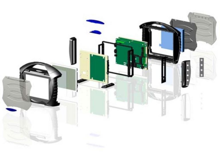
Designing a user interface or HMI assembly can be overwhelming and time consuming. That’s why CSI Keyboards has become the one stop shop for human machine interface (HMI) and front panel interface assemblies. CSI Keyboards has over 35 years of experience specializing in the integration of the below technologies into complex user interface turnkey keypad assemblies. Our broad product line and engineering expertise allows for us to design and manufacture fully integrated interface solutions at a lower cost and better flexibility for the customer. Customers all over the world rely on CSI Keyboards’ expertise to design, manufacture, and assemble the whole turnkey user interface.
From membrane switches and elastomer rubber keypad assemblies, to touch screens and touch panels integrated with displays, CSI Keyboards specializes in designing and fully integrating a variety of components and customized parts into a complete custom turnkey keypad assembly and user interface for your company. We can take your concepts and bring your product to fruition providing you with the complete plug and play keypad package from one dependable and experienced source.
Benefits of a Full Turnkey HMI Assembly
So What Can Actually be Integrated into my HMI?
The following is a list of some of the components and electronics that we’ve integrated into some of our HMI and User Interface Assemblies: