Common Membrane Switch Terminology

Common Membrane Switch Terminology

ACTUATION FORCE

The pressure required for actuating the circuit of a membrane switch or rubber keypad.

ADHESION

The strength of the molecular attraction bond of one material to another determined by the surface energy in each material.

BACKERS

Incorporating backers into membrane switch assemblies for mounting or rigidity purposes. The most commonly used material is aluminum which can be supplied with a variety of hardware installed. Other backer options include G10, stainless steel, polycarbonate or acrylic materials.

BACKLIGHTING

Lighting of membrane switches using LEDs, light guide film, fiber optics or EL panels.

BREAKDOWN VOLTAGE

The minimum voltage at which the insulation between two conductors begins to fail.

CARBON OVERCOAT

Ink that consists of prepared suspensions of carbon black and is applied over silver circuitry to mitigate the possibility of silver migration. Typically used on the flex tail contacts which is the area on the flex circuit most susceptible to silver migration.

CIRCUITRY

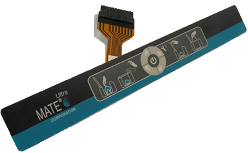
Electrical circuit used to operate a membrane switch typically either printed silver, copper flex or printed circuit board based.

CONDUCTIVITY

A material’s ability to allow the flow of electrons.

COPPER FLEX

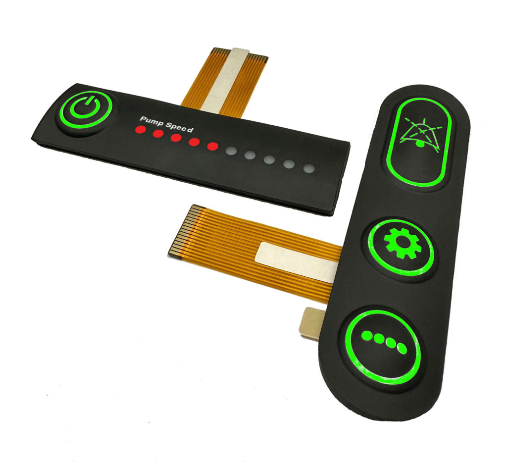
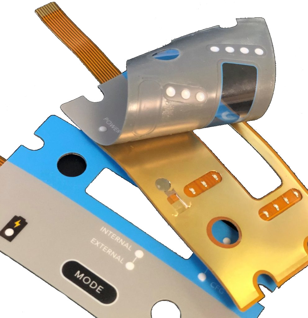
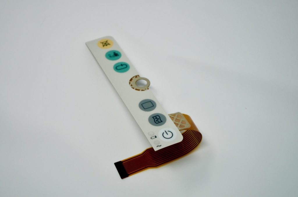
A type of circuitry used in membrane switches produced using polyimide (Kapton) as the base material. Manufactured by laminating a thin sheet of copper to a flexible film substrate, the copper is then chemically etched away, leaving the copper traces. An additional layer of polyimide is laminated to the circuit leaving the gold contacts exposed. Also known as Kapton circuits, they have become the superior choice over printed silver especially for outdoor applications due to their excellent dielectric strength, thermal stability, chemical resistance and flexibility.

CROSS-OVER

A conductor intersection where the traces are kept separated and insulated by dielectric material insulator.

DEAD FRONT

A cosmetic feature of a graphic overlay in which an artwork feature is only visible when backlit.

DIELECTRIC / DIELECTRIC INKS

An insulating or non-conducting medium. The inks are used for printing protective patterns on conductive printing to isolate selected areas from electrical contact with other conductors. Typically used for cross-overs and tail insulation.

DOMES

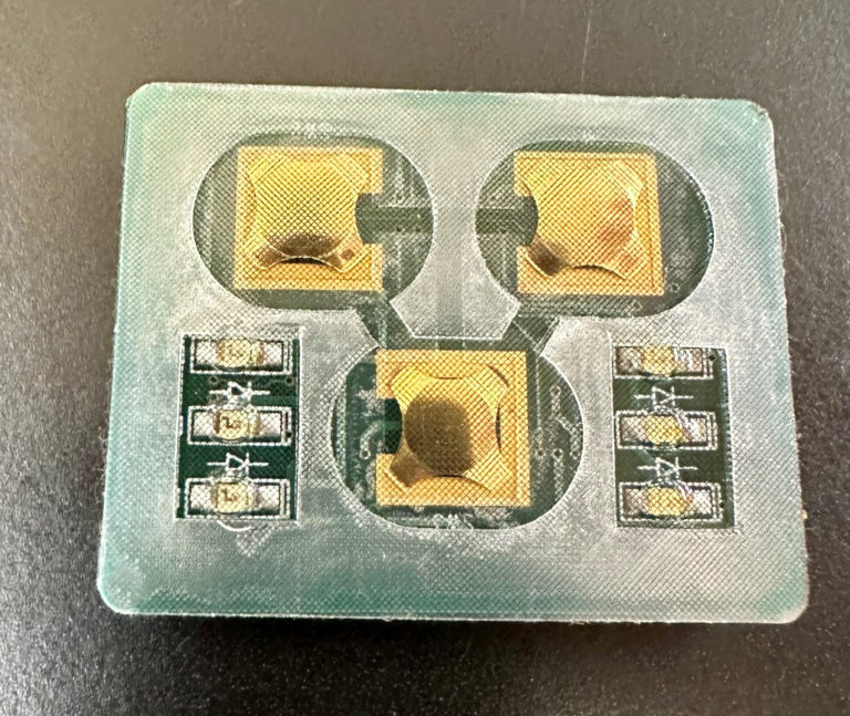
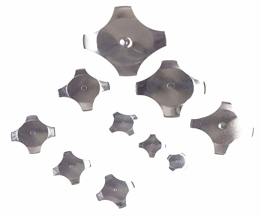
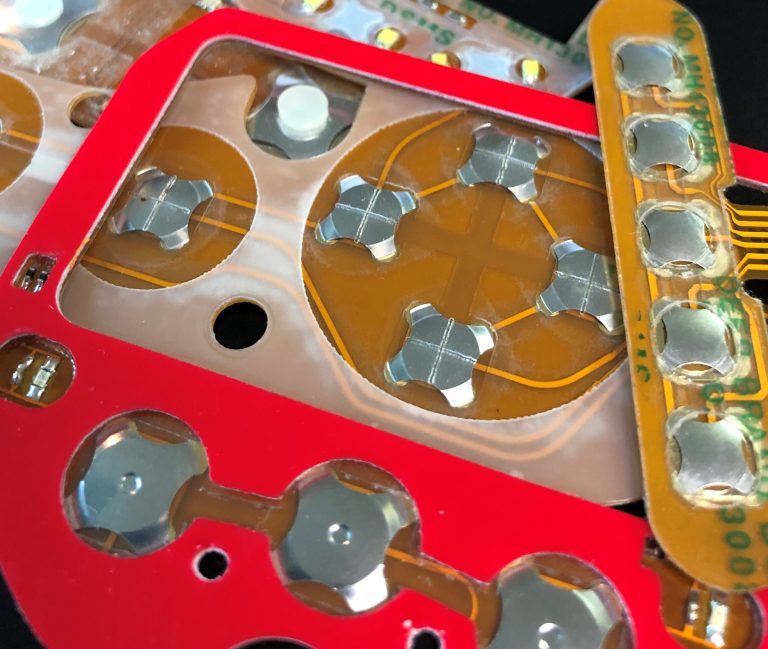
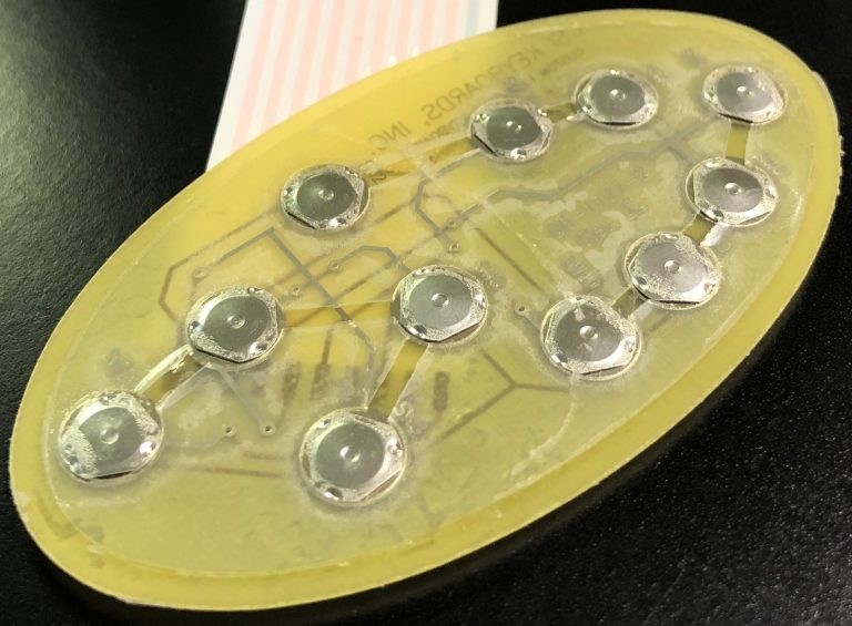
A tactile metal dome (or a snap dome) is a normally open momentary contact that provides a crisp tactile feel letting the user know the button was pressed/actuated. Polydomes can also be utilized if necessary.

DOME RETAINER

An adhesive layer made to hold metal domes in the key-switch.

EMBOSS

Method of raising an aspect or aspects of the overlay material to accentuate key surfaces through mechanical and thermoforming of graphical features. Typically used for keys and/or LED indicators.

ENVIRONMENTAL SEALING

Utilizing proprietary design features in order to seal a membrane switch or rubber keypad. Such features include frame sealing, the use of copper flex circuitry and rubber gasketing.

GRAPHIC OVERLAY

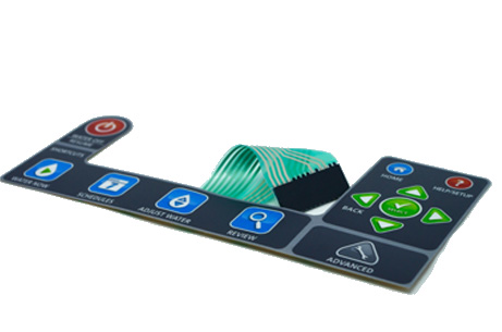
The decorative front layer of a membrane switch or control panel.

KEY HEIGHT

The distance from the highest point of a key to the base of the keypad.

LIGHT EMITING DIODE (LED)

Assembled to the membrane switch circuitry to illuminate a feature or features on the keypad.

PINOUT

The schematic that describes the circuit output requirements for membrane switches. Also known as a wire diagram.

PRESSURE SENSITIVE ADHESIVE (PSA)

Adhesive materials that bond through the application of pressure without the need for heat or solvents.

REAR PSA

A pressure sensitive adhesive applied to the back of a membrane switch for mounting purposes. Different types of rear PSA can be utilized depending on the application and bonding surface.

SHIELDING

Utilizing methods for incorporating ESD/RFI/EMI shielding within the membrane switch layers.

SECOND SURFACE PRINTING

Practice of printing a graphic overlay from the bottom in reverse, so the outer layers protect the graphic.  This is particularly useful in membrane switch applications where the graphic overlay experiences abrasive wear.

SILVER INKS

Tiny particles of actual silver suspended in various substrates that produce conductive patterns on rigid and flexible substrates.

SPACER LAYER

A membrane switch adhesive layer separating the electronic circuit layers with button/switch openings.

TAIL BREAKOUT

The location of the tail exit on the back of the membrane switch.

VENTING

Membrane switch openings connected to one another to seal the switch from moisture and other contaminants without venting externally. External venting is also an option if the design allows for it.

WINDOWS

Utilizing the base clear overlay to incorporate windows in a membrane switch typically for displays. Can utilize hardcoats or textures depending on the application. Incorporating a reinforced opti-bond window is also a common technique for windows susceptible to excessive abuse.

WIRE DIAGRAM

A diagram showing the desired connections to the pinout connector.
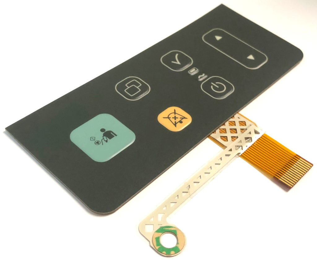
Membrane Switch Copper Flex Circuitry
Membrane Switch Copper Flex
Backlit Rubber Keypads
Membrane Switch Silver Circuit
Sealed Rubber Keypad

Emulating Seven Segment Displays in Membrane Switches

Emulating Seven Segment Displays in Your Membrane Switch or HMI

Are you looking to integrate a seven segment display or displays into your interface but are encountering space constraints and/or trying to keep costs down? 

CSI has years of experience emulating seven segment displays using LEDs, light guide film and light blocking features. We also utilize additional methods including light “piping” features within the layers of the membrane switch. We can integrate LEDs of any color and any window color to give you the exact aesthetic you are looking for in your product. The result is a thinner membrane switch package size at a much more cost effective price.

Advantages:


1. Thinner membrane switch package size.

2. More cost effective than using actual seven segment displays.

3. Can integrate into a flexible circuit (versus printed circuit board).

Of course, if you want to use actual seven segment displays that is also an option but will most likely require a printed circuit board design (versus a thinner flexible circuit) and an overall thicker membrane switch package. The CSI engineering team can assist you in this process in order to ensure you get exactly what you are seeking for your interface.

Seven Segment Displays in Membrane Switches

Preventing Newton Rings in Your Membrane Switch or HMI

Preventing Newton Rings in Your Membrane Switch or HMI

If you’ve ever designed a product with a screen or display you’ve most likely encountered Newton rings. Newton rings are a phenomenon in which a series of concentric colored bands are observed between two pieces of glass or glass-like materials and a layer of air exists between them. The phenomenon is caused by the interference of light waves from both top and bottom surfaces of the air film between the two pieces of glass or glass-like materials. In the case of membrane switches, it is typically the space between the graphic overlay window and a display.

Therefore, it’s critical that Newton rings are accounted for and addressed during any sort of design and assembly involving screens or lenses.

There are essentially three methods for addressing Newton rings:

1. Design an air gap between the graphic overlay window and the display screen.

2. Optically bond the graphic overlay window to the display screen.

3. Print very fine, clear dots on the back of the graphic overlay window.

There is no right or wrong method for addressing the phenomenon and it is really contingent on the product and design. But it’s of the utmost importance that it’s addressed! The CSI engineering team can assist you in this process in order to ensure that there is zero probability of this phenomenon from occurring in your product.

Newton Rings Membrane Switch

The Case Against Printed Silver Circuitry: Embedded Components

The Case Against Printed Silver Circuitry: Embedded Components

We recently had a customer approach us experiencing issues with one of their printed silver circuit membrane switch designs. The customer sent us some samples for our analysis and it was found that the LEDs would function as expected in a flat state but when the tail was pulled back or the keypad flexed, the parts exhibited enough internal force to also flex the LED causing the LED to either fail and/or flicker in some cases. It was then determined that the LED issues were caused by the silver epoxy fracturing where it joins the printed silver ink circuit trace. It wasn’t the LEDs that were failing, but actually the method in which the LEDs were applied to the circuit that was ultimately failing.


When first designing this keypad assembly, the available flexible circuit technology at the time was printing silver ink on polyester film and affixing LEDs to the silver circuit using a silver epoxy paste or glue.  Although, printed silver is still a common method even to this day, it does lack some robustness and does not always achieve the same results for all customers. There are a host of reasons why it can fail, but when it does it is best to upgrade to a more robust design (polyimide circuitry). With the availability of cost effective copper on Kapton flex circuits, we are now able to provide soldered LEDs which are far more reliable than having to rely on an epoxy assembled LED. Being able to traditionally solder LEDs provides an infinitely more reliable part as both the joint and the adhesion of the copper to the polyimide (Kapton) base substrate are much more durable. 


CSI utilizes copper flex circuitry on many similar keypad assemblies that are used in the automotive industry, medical devices, military, marine, etc. Many of which reside in harsh environments and in most cases have withstood and passed extensive testing by our customers before entering production. It is a time-proven and tried-and-true design for CSI and one we have been successfully utilizing for a decade. 

Membrane Switch Defined

Membrane Switch Defined

What is a Membrane Switch?

membrane switch is an interface between man and machine, enabling an operator to communicate with equipment, instrumentation, or machinery. A membrane switch is a printed or etched electronic circuit that uses pressure to open and close a circuit. The membrane switch circuitry can be: screen printed using conductive inks which are typically made of silver or carbon, etched copper on Kapton, or can be printed circuit board based. The membrane switch overlay is typically made of polyester, polycarbonate, or molded silicone rubber. Membrane switches are part of a range of devices considered to be user interfaces or human machine interfaces (HMIs) along with touch screens and mechanical switches.

Membrane Switch Construction

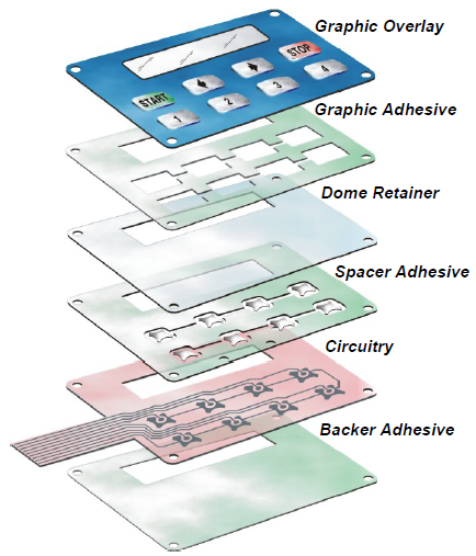
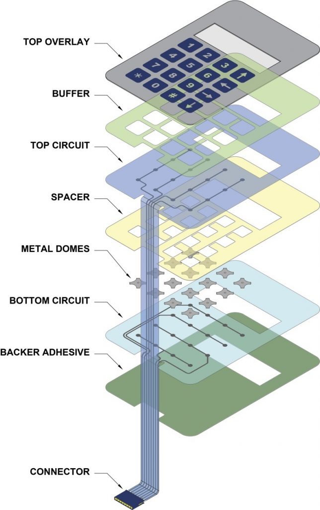
A typical membrane switch assembly typically consists of six to seven main layers:

  • Graphic Overlay – Graphic overlays are typically constructed of polyester, the material of choice due to its superior chemical resistance and flex life compared to polycarbonate. CSI can either digitally print, screen-print, or employ a combination of both methods to insure you get the right colors, textures, and finishes your Silver Flex membrane switch design requires.
  • Overlay Adhesive – The overlay adhesive layer bonds the graphic overlay to the top circuit layer. This overlay adhesive is typically an acrylic adhesive, selected for its durability and ability to maintain adherence in atypical environments, such as moist environments.
  • Top Circuit Layer – Typically a .005″ – .007″ heat-stabilized, polyester printed layer with silver-filled, electrically conductive inks and dielectric inks. This layer can also encapsulate metal domes or incorporate polydomes, which are used to achieve tactile feedback, an important design consideration impacting usability.
  • Circuit Spacer – This layer separates the top circuit from the bottom circuit, so the switch remains normally open until the keypad is pressed. The circuit spacer is a polyester spacer with adhesive on both sides.
  • Lower Circuit Layer – The lower circuit layer is typically a .005″ – .007″ heat-stabilized, polyester-printed layer with silver-filled electrically conductive inks and dielectric inks. This layer terminates as a flexible tail that serves as the interconnect to controller PCB’s or other electronics.
  • Rear Adhesive Layer – This adhesive layer bonds the entire membrane switch package to the product enclosure, housing, or to a rigid support panel. CSI can specify the appropriate adhesive type and thickness to bond your membrane keypad to your equipment.
  • Rigid Support Layer – This optional layer can add structural integrity to the membrane switch assembly. Materials can be aluminum, FR-4, steel, etc. Mounting hardware such as studs and standoffs can also be utilized in this layer.
Membrane Switch Guide

Copper Flex Membrane Switches

The Copper Flex Membrane Switch constructions are ideal for smaller designs, where space is at a premium, or where dense circuit patterns or trace routing limitations exist. Copper Flex membrane keypads utilize silver or copper layers which are laminated to a dielectric layer and etched away.

This switching technology combines the ability to accommodate the complex circuit patterns of a FR4 rigid printed circuit board with the flexibility of a membrane switch. Copper Flex keypads also have the advantage of being able to “hard” solder both active and passive components into the assembly, making it a good choice in high-vibration environments.

Copper Flex membrane switch panels can be produced using polyester or polyimide (Kapton) as the base material depending on your interface requirements. A very thin sheet of copper is laminated to the flexible film substrate then chemically etched away, leaving copper traces. 

Copper Flex membrane switches offer you a variety of design options:

  • Single and double sided designs
  • Lower electrical resistance and higher conductivity vs. traditional Silver Flex membrane switches
  • Tight trace routing capabilities
  • Thin profile and flexibility of Silver Flex membrane switch
  • Plating options can be tin-lead, nickel, or gold
  • Tactile and non-tactile with either metal or polyester tactile domes
  • LED’s and other components can be soldered
CSI Keyboards Medical Membrane Switch

PCB Based Membrane Switches

The PCB Membrane Switch construction utilizes a printed circuit board (PCB) which can serve a dual purpose in your membrane switch design. PCB Switches are typically more costly than Silver Flex membrane keypads, but can accommodate dense circuit patterns and more complex circuit patterns compared to Silver Flex membrane keypads.

A PCB membrane switch also allows the electronic components to be “hard-soldered” into the PCB, whereas membrane switch components are placed using a polymer thick film conductive paste. With a PCB membrane switch, the PCB can serve as a rigid backer, and is also a very durable and reliable method to incorporate LED’s, resistors, LCD’s and other components.

CSI Keyboards PCBA Rubber Keypad

PCB membrane keyboards offer you a variety of design options:

  • Tactile and non-tactile with either metal or polyester tactile domes
  • Pillow or rim-embossed graphic overlays
  • Embedded LED’s that are soldered directly into the PCB
  • Fiber Optic backlighting
  • EL – (Electroluminescent backlighting)
  • Rigid backers such as aluminum and FR4
  • EMI/RFI shielding
  • Unlimited choice of connectors, which can be soldered directly into the PCB

Silicone Elastomer Rubber Keypads

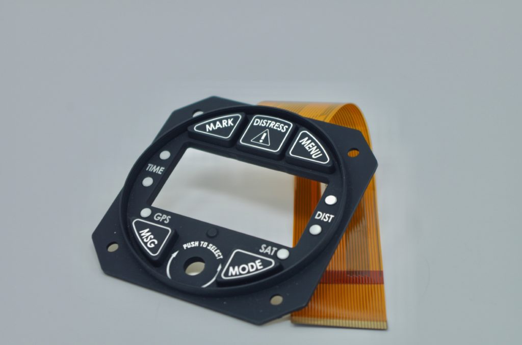
Silicone rubber keypads use compression-molded silicone rubber with conductive carbon pills or with non-conductive rubber actuators.  They have exceptional resistance to extreme temperatures and aging, making them an ideal choice if reliability is a prominent concern due to likely environmental influences.

A rubber membrane switch uses compression-molded silicone rubber with conductive carbon pills or with non-conductive rubber actuators. Rubber keypads are relatively inexpensive on a per-piece basis, but require fairly expensive tooling, usually making them a design choice for higher-volume projects.

Silicone rubber keypad switches have numerous features that set this type apart from other traditional membrane switch designs. Some of the main differentiating features of this type make the silicone rubber keypad switch an ideal choice for applications requiring more durability or better resistance to exposure to moisture, chemicals, or other compounds.

Molded rubber keypad: copper flex circuit based with domes and backlit keys

Some of the primary distinctive features of silicone rubber keypad switches include:

  • Work as a conductive shorting device for Silver Flex membrane switchesPCB membrane switches, and Copper Flex membrane switches
  • Can utilize carbon pills, non-conductive rubber actuators, or stainless steel tactile domes
  • Actuation forces and switch travel can be customized
  • Any shape or size can be designed
  • Multiple colors can be achieved by flow molding the color during the compression-molding process
  • Rubber keypad top graphics can be customized by screen-printing
  • Rubber keypad switches can be PU spray-coated for enhanced durability
  • Rubber membrane switches have excellent weatherability for outdoor use
  • Can be designed to seal the keypad assembly from moisture and contaminants
  • Silicone rubber is resistant to chemicals and moisture
  • Laser etching the rubber keypads can allow for backlighting individual keypads
  • Backlighting options

Utilizing Mesh for Keypad EMI Shielding

Utilizing Mesh for Keypad EMI Shielding ​

Do you have a product that has stringent EMI shielding requirements? CSI can integrate EMI mesh into your keypad assembly using the finest woven blackened wire mesh. The mesh is blackened to make it suitable for optical applications such as applying over displays or under windows. 

EMI protection will be provided by covering the entire keypad, display and LED conductors, etc. with wire mesh. The mesh is typically 80 x 80 density, of .0011 inch diameter stainless steel wire strands.  It is an interwoven fabric, silver coated, and then blackened. The mesh shall be in direct electrical contact when attached to the enclosure. The woven mesh is highly conductive for the best EMI shielding effectiveness and is even and very black avoiding highly reflective un-blackened wires and discolorations.

Integrating the Mesh into the Design:

  1. The mesh is die-cut to the shape of the keypad and then assembled into the internal layers of the keypad assembly.
  2. CSI will work closely with you in determining the best method to make direct electrical contact between the EMI mesh and your product when the keypad is assembled to your enclosure.
Membrane Switch with EMI Mesh

Redesigning your Existing Membrane Switch

Redesigning your Existing Membrane Switch​

Every week, we are approached by a customer that is having issues with a membrane switch or keypad designed by another manufacturer. More often than not, the membrane switch was not engineered properly when it was originally developed. Typically, the membrane switch is failing out in the field due moisture ingress and lack of sealing characteristics.

Because this is such a common occurrence, CSI has a seamless process in place for redesigning your current membrane switch without having to completely reinvent the wheel. We can work closely with your company in designing a drop-in replacement that will not require any product redesign or any changes for that matter on your end. CSI will update and upgrade all of the critical internal layers giving you the environmental sealing required while leaving the external layers untouched – leaving you with a completely sealed product upgrade that can be smoothly incorporated into your existing production line.

So what you waiting for?! If you are unhappy with your current membrane switch, now is the time to make the change. Reach out to CSI today to get the ball rolling and eliminate these headaches once and for all!

What are the Internal Layers of Membrane Switches?

What are the Internal Layers of a Membrane Switch?​

We all know about the graphic overlay layer which is the top surface of the keypad that always gets the most attention (and rightfully so).  But what’s going on behind the scenes in the sub-assembly of the membrane switch?  Let’s find out.

Dome Retainer Layer

The dome retainer layer is somewhat self explanatory. The primary function of this layer is hold the metal domes in place and position. It is typically manufactured from polyester film material.

Spacer Layer

The spacer layer is used to created a break in contact between the two conductors of the switch. This allows the switch to have its open position. The spacer design typically includes vents or channels to prevent air entrapment in the layers when the keys are pressed or actuated.

Circuit Layer

The circuit layer is the electrical aspect of a membrane switch where the conductive traces are applied using one of the two main methods of application: screen printing and photochemical etching.

  • Screen Printing or Printed Silver Circuitry: Silver conductive ink is flooded on the stencil placed above a substrate (typically polyester film).
  • Photochemical Etching or Copper Flex Circuitry: Copper laminated substrate is selectively created through photolithography and a chemical etching process.

Mechanically Mounted & Fastened Keypads

Mechanically Mounted & Fastened Keypads

While the majority of keypad assemblies are simply adhered to the end product using rear pressure sensitive adhesive (PSA), in some cases the product design calls for mechanical mounting. Mechanically fastening the keypad assembly not only provides additional mounting support and rigidity, it also prevents the keypad from being removed or pried from the front (in many cases for security purposes) and allows our customers the flexibility to remove the keypad assemblies out in the field when required. 

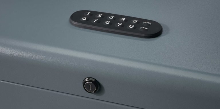
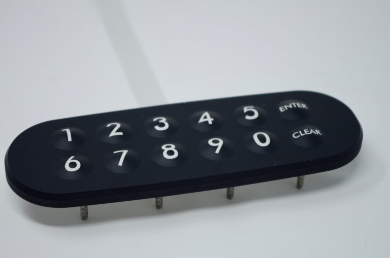
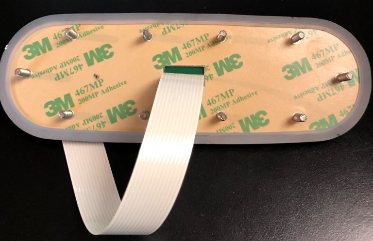
The rubber keypad assembly shown below is used in an outdoor lockbox application and has the following design features: 

  • Mechanically fastened using 10 PEM studs that are integrated into the metal backer.
  • Backlit keys using LEDs, light guide film, light piping and laser etching technology.
  • Environmentally sealed utilizing the rubber which wraps around the entire assembly acting as a sealed gasket.
  • Tactile keys using metal domes.
  • Cable assembly with female connector soldered and sealed to the PCB for connection to customer’s PCB. 
Rubber Keypad Mounted to Outdoor Lock Box
Rubber Keypad with PEM Studs for Mounting
Rear View of Rubber Keypad with PEM Studs

How to Choose the Right Dome for a Membrane Switch

How to Choose the Right Dome for a Membrane Switch

Choosing the “right” dome for a membrane switch may seem daunting, but rest assured, it is more straightforward than you might initially think. Firstly, what are metal domes? Metal domes are used in membrane switches and keypads to enable and facilitate the electrical connection from the keypad to the product itself. Or in other words, how the user of a device initiates a specific electrical function on the product. 

Electrical switches are necessary in almost every HMI (human-machine interface) device or product. No membrane switch is the same and all are used in a unique environment, therefore it is critical that the most suitable dome is chosen for the specific application and environment. For instance, if the product is used in an industrial setting and the user will be wearing gloves: a dome larger in size with a higher force & stronger tactile feedback would be ideal. Or if the membrane switch will be used in a nursing home setting and the user will typically be older in age: a dome with a lighter force (easier to press) would be best suited.

Our CSI engineers will work closely with you in deciding which dome is best for your application. We understand that the tactile feel of a key is very subjective, so typically will mock up multiple sample keypads with different dome options in the prototype stage of the design. This allows our customers to make a decision through a more “hands-on” approach. It’s also important to understand that the dome happens to be one of the easiest components of the membrane switch design to change-out & replace throughout the design cycle and even after the keypad is in production (ie so you are never stuck with a specific dome).

Dome Characteristics & Options:

Size: 

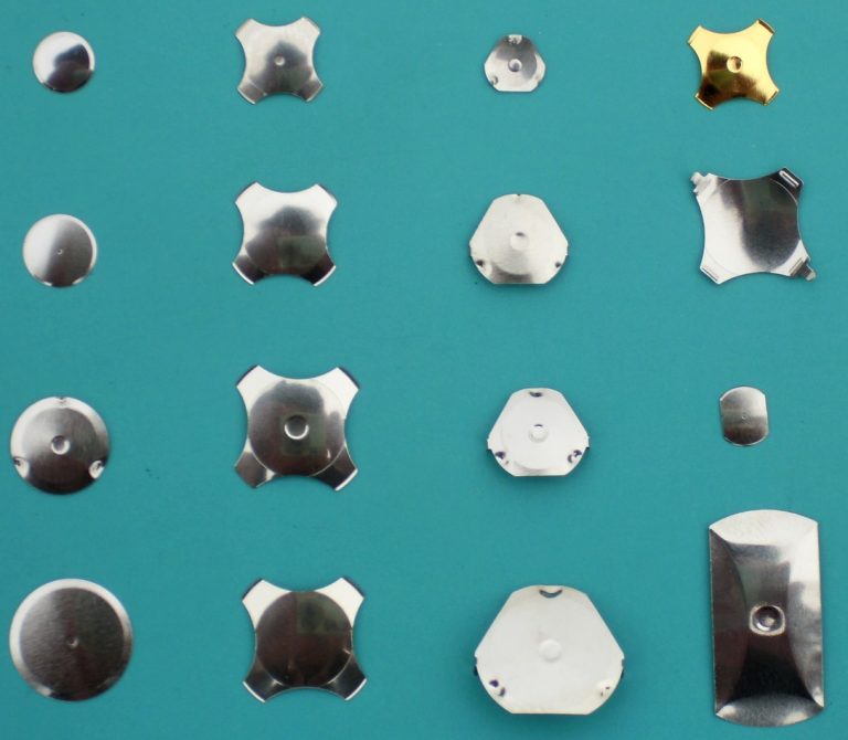
Measured in diameter and height of the dome. The size of the keys on the membrane switch will ultimately determine the size of the dome required for the application. Domes sizes range from 6mm up to 20mm. Height is dependent on size and ranges from .25mm up to 1.45mm.

Shape:

  • Four legged
  • Triangle
  • Round 
  • Oblong
  • Custom
 

Actuation Force: 

The actuation force is one of the most critical characteristics when choosing a dome. Actuation or trip force is the minimum force needed to depress the dome and is measured in grams. Actuation forces range from 40g up to 2250g. 

Lifecycles: 

Domes have come a long way since their inception. Originally, domes were only rated for thousands of cycles. The standard for domes is now at least one million cycles, with specialized domes rated for at least five million cycles. No matter the application, there is a dome that can meet your lifecycle requirements.

Dimple or Non-Dimpled: 

Looking at a variety of domes for different applications, users may notice a little dimple located in the center of the dome (see pictures to the right). The dimple is a small concave feature located on top of the dome, and can be as deep as 0.2 mm (0.008 in.). The purpose of the dimple is to provide better electrical characteristics and to reduce contact bounce..