What are UV Resistant Coated Membrane Keypads?

What are UV Resistant Coated Membrane Keypads​

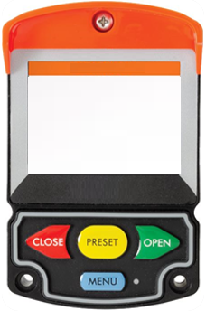
Many of the user interface products designed and manufactured by CSI will eventually live in extremely harsh environments. Some being exposed to UV exposure from the sun for days, months or even years at a time. Luckily, there are methods to protect the keypad from the effects of the sun. One of these methods is using a UV Resistant Coating. 

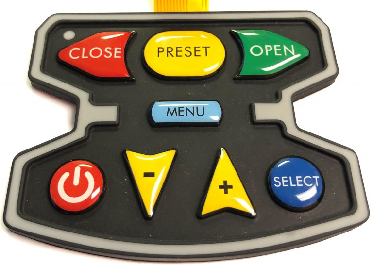
A UV resistant coating is typically applied to the keys. The coating is glossy in appearance and looks very similar to epoxy coatings that were once used on membrane switches. The major difference between the UV resistant coating and the epoxy coating however, is that the epoxy was not durable. Over time, the epoxy not only became embrittled but it tended to discolor and yellow. 

The UV resistant coating is designed with special barrier resins and compounds that are activated with ultraviolet light. Once activated, they prevent any damage from occurring to the coating or the base material of the keypad.

The UV resistant material’s  “glossy-like” look also enhances the appearance of keypads. The glossy and clean look of the material really makes the product snap and stand out. Between the UV resistant benefits and the enhanced aesthetics, using the UV coating is really a no-brainer when designing a keypad that is going to be used outdoors. 

What Industries Does CSI Serve?

Industries Served

  • Medical : 25%
  • Military : 20%
  • Industrial : 15%
  • Aerospace : 10%
  • Marine Controls : 10%
  • Food Equipment : 10%
  • Agricultural Controls : ≤5%
  • Other : ≤5%

The CSI Advantage

Why CSI?

  • Speed & Efficiency:
    • Concept to Design: ≤ 2 weeks
    • Design to Part: 4-5 weeks

  • Engineering Team: solely focused on keypad and user interface designs

  • Experience: 35+ years, 2500+ custom HMI products, 150+ new designs per year

  • Local Support: Sales, Product Management, Engineering, Quality, Manufacturing

  • Local On-Site Manufacturing, Assembly, Quality, Shipping Teams: ensures parts are built, tested, and shipped to conform to the highest standards

  • Overseas Manufacturing: utilized for larger production volumes and to ensure we can offer the most competitive pricing to our customers

CSI Develops Heavy Duty Sealed Keypad

CSI Develops Heavy Duty Sealed Keypad

Product: Mounted on the outside of an auxiliary vehicle exposed to: water, dust, dirt, ice, rock bombardment, etc.

Case: Customer approached CSI with a keypad that was failing out in the field.

Product Issues:

  • Keypad failing out in the field due to moisture ingress
  • Domes collapsing
  • Graphic overlay fading from UV exposure
  • Lack of tactile response when pressing keys
  • Keypad peeling off of surface
 

CSI Final Solution:

  • 100% Environmentally Sealed Keypad (as a standalone part)
  • Durable and Ruggedized Rubber Keypad Design
  • UV Resistant Keys
  • Improved the Design & Tactility of Keys
  • Upgrade Rear Adhesive for Stronger Adhesion to Surface

The CSI Process

The CSI Process

Concept: The process typically starts with a customer concept which can range from something as simple as a description or a sketch with a list of requirements right up to full keypad drawings.

Design: Once we have enough information on the design, we work up a quote and proposal for the project.  CSI then works on a drawing package which typically takes about 2 weeks depending on complexity of design.  During those two weeks, we are interfacing back and forth with customer. 

Prototype: Once customer signs-off on the design, we built prototype parts which takes about 4-5 weeks.  Because it’s a custom product, there are usually some minor tweaks that take place during the prototype stage such as tactile feel of keys, colors, etc. 

Production: After prototypes are approved, we enter into production. 

Logistics: Work closely with our customer’s procurement team to ensure the customer receives the product when and where they need it. 

Sustainability: After the part has entered into production, CSI sustains and supports the user interface throughout the life of the product.  CSI is still supporting products that were originally designed 37 years.  Some products having gone through some design improvements, while others being built exactly as they were in 1983.

Membrane Switch Connector Options

Membrane Switch Connector Options

Membrane switch connectors connect the keypad to the actual product, device or machine. Connectors consist of both contacts and molded plastic housings. Membrane switches are typically designed with flexible tails that are cut from the circuit material which is inserted or connected to a printed circuit board with a variety of connectors. Alternatively, the tail can be designed and prepared to connect with a Zero Insertion Force (ZIF) connector on the customer’s PCB. ZIF connectors have become extremely popular and industry norm. If the membrane switch is not flexible circuit based but instead, a PCB based keypad design, a flexible tail can be hot-bar soldered to the PCB or any connector can be soldered directly to the printed circuit board. Although both are rarely used in the modern era, solder tabs and discrete wires are both additional options.

Connector Options:

Most Common Options:
Bare Tail: connects to .100” center ZIF style connector
Female Standard Connector: connects to a .100” center, .025” square posted header
Female Latching Connector: connects to a .100” center latching header

Bare Tail for ZIF Connector

bare zif connection membrane switch

Female Standard Connector

female connector membrane switch

Female Latching Connector

female latching connector membrane switch
Other Options:
  • Male Standard Connector: interfaces to a .100” center female header
  • Male Latching Connector: interfaces to a .100” center latching header
  • Solder Tabs: .100” centers and can be directly soldered to PCB or wires
  • Discrete Wires

ZIF Connectors

ZIF connectors are assembled to the PCB end and therefore there is no physical connector on your membrane switch side (the end of the flex tail is bare). ZIF connectors typically have a low profile, are lightweight, secure, and removable connections. ZIF connectors are appropriate for more complex applications and allow for higher levels of integration. The tail of the circuit is inserted into the ZIF connector to create the contact, and a stiffener is laminated under the tail to ensure stability and maintenance of the electrical contact. ZIF connectors may have anywhere from 2 to 30 positions on a single row, and distances of between 1mm and 2.54 mm are available.

Crimpflex & Memcon Connectors

Crimpflex and Memcon connectors conform to Berg, Molex, and Amp membrane switch connecting specifications by utilizing common pins in a specific housing to meet connection requirements. The Crimpflex and Memcon crimping presses are dedicated to the manual and pneumatic crimping of male and female contacts and are known for their reliability, ruggedness, simplicity of use, speed, and precision. The contacts ensure mechanical retention and electrical contact by piercing the conductor in six points. The contacts are available in male, male solder tab, and female versions; the female contacts are selective gold or tin-plated. Standard housings are available in the OF series, which fits with the most common interfaces, or the OM series, which interfaces with cables and comes with an locking system that can be oriented to meet your specifications.

Hot Bar Soldered Tails

This type of connection has become very common with printed circuit board based membrane keypad and membrane switch designs. A copper flex tail is hot bar soldered directly to the PCB. The tail can then be inserted directly into a ZIF connector on the customer’s PCB. Allows for a lot more flexibility in the design and tolerance when plugging the tail into the board versus using a connector.

Male, Female, or Solder Tab Housings

These types of connectors are considered to be more reliable against heavy shock and vibration. They also are known for more ease of assembly. With a much larger connection, male, female, and solder connectors have pins crimped to the circuit and are available with many different housing features. The tail pitch is available in .100” spacing.

Membrane Switch Construction

Membrane Switch Construction


Typically a membrane switch assembly typically consists of six to seven main layers:


  1. Graphic Overlay – Graphic overlays are typically constructed of polyester, the material of choice due to its superior chemical resistance and flex life compared to polycarbonate. CSI can either digitally print, screen-print, or employ a combination of both methods to insure you get the right colors, textures, and finishes your Silver Flex membrane switch design requires.
  2. Overlay Adhesive – The overlay adhesive layer bonds the graphic overlay to the top circuit layer. This overlay adhesive is typically an acrylic adhesive, selected for its durability and ability to maintain adherence in atypical environments, such as moist environments.
  3. Top Circuit Layer – Typically a .005″ – .007″ heat-stabilized, polyester printed layer with silver-filled, electrically conductive inks and dielectric inks. This layer can also encapsulate metal domes or incorporate polydomes, which are used to achieve tactile feedback, an important design consideration impacting usability.
  4. Circuit Spacer – This layer separates the top circuit from the bottom circuit, so the switch remains normally open until the keypad is pressed. The circuit spacer is a polyester spacer with adhesive on both sides.
  5. Bottom Circuit Layer – The lower circuit layer is typically a .005″ – .007″ heat-stabilized, polyester-printed layer with silver-filled electrically conductive inks and dielectric inks. This layer terminates as a flexible tail that serves as the interconnect to controller PCB’s or other electronics.
  6. Rear Adhesive Layer – This adhesive layer bonds the entire membrane switch package to the product enclosure, housing, or to a rigid support panel. CSI can specify the appropriate adhesive type and thickness to bond your membrane keypad to your equipment.
  7. Rigid Support Layer – This optional layer can add structural integrity to the membrane switch assembly. Materials can be aluminum, FR-4, steel, etc. Mounting hardware such as studs and standoffs can also be utilized in this layer.

General Considerations When Designing a Membrane Switch

General Considerations When Designing a Membrane Switch


Environmental

• What temperature and humidity range will this product experience?
• What types of contaminants or chemicals will come into contact
with this product?
• Will this product be subjected to moisture and/or U.V. exposure?

Mechanical

• Will tactile response be required?
• To what material will the switch be laminated?
• What number of actuations will this product receive?

Electrical

• How many contact points will there be?
• What type pinout or matrix will be used? (common bus, X-Y matrix)
• What closed loop resistance will be acceptable?
• Will electrostatic or EMI shielding be necessary?

Appearance

• Will edges be exposed, recessed, or covered with a bezel?
• Will embossing be required?
• Will there be different parts to the same product? (sets)
• How many colors will be needed?

What is Required for Creating a Membrane Switch Blueprint? 

Blueprint for Designing Membrane Switches


  • Overall size of the part
  • Keypad centers
  • LED locations
  • Diameter of corners
  • Size and Location of Cutouts
  • Size and Location of Windows
  • Location of Tail Exit Point
  • Location of Graphic Entities
  • Electrical Schematic
  • Identify “Pin 1”
  • Color specifications
  • Tail location and length

Benefits of Using Membrane Switches

Benefits of Using Membrane Switches


Thin Construction: Membrane switches are extremely thin in construction, especially in comparison to other technologies such as mechanical switches.

Environmentally Sealed Construction: Membrane switches can be designed with a sealed construction design preventing moisture or contaminant ingress.

Low Profile: Membrane switches have a low profile surface which allows for easy cleaning.

Cost Effective: Membrane switches are extremely cost effective especially in comparison to other user interface technologies. 

Customizable: Membrane switches are easy to customize, giving customers the ability to achieve the look and feel that they desire including customizable graphics, domes, keys, texture, size/shape, windows, etc.