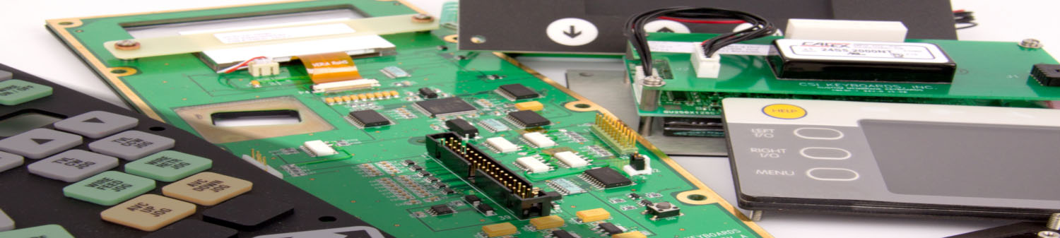
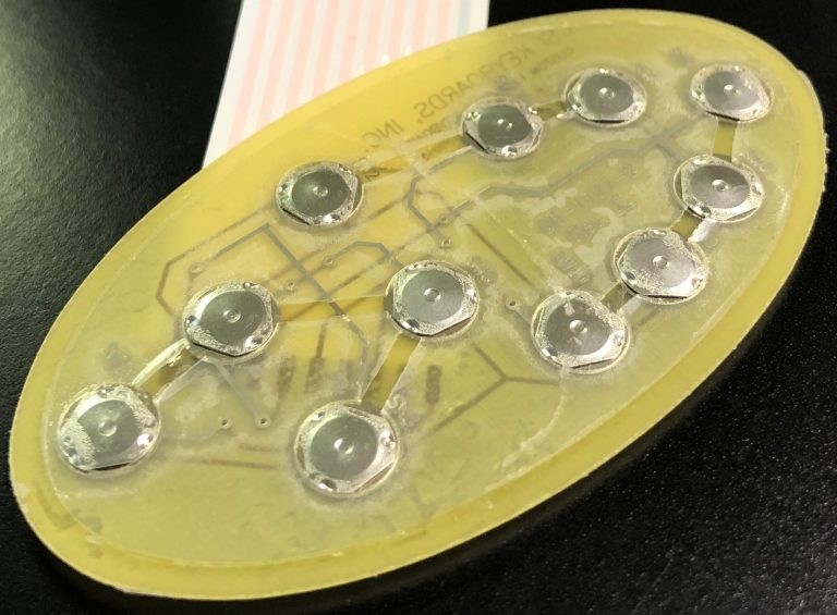
CSI Keyboards uses copper flex circuitry in the majority of our custom keypad designs due to its excellent dielectric strength, thermal stability, chemical resistance and flexibility. Copper flex, also known as Kapton circuits, have become the superior choice over printed silver especially for outdoor applications. A printed silver circuit can be replaced with a copper and polyimide construction with minimal additional cost. Copper flex circuitry construction designs offer a significant advantage over printed silver.
Below are some key flex circuit terms that you should know:
Access Hole – A series of holes in successive layers of a multilayer board, each set having their centers on the same axis. These holes provide access to the surface of the land on one of the layers of the board.
Additive Process – A process for obtaining conductive patterns by the selective deposition of conductive material on clad or unclad base material.
Annular Ring – The ring of exposed solder or copper around a through hole.
Buried Via – A plated through hole buried within internal layers of a circuit. There is no direct access to the via.
Blind Via – A plated interconnection from one layer to an adjacent layer through a fixed depth LASER drilled opening.
Cantilevered Leads – Unsupported conductors extending from an edge of a flex circuit.
Circuit – A number of electrical elements and devices that have been interconnected to perform a desired electrical function.
Coverlayer – Insulating layer usually bonded with adhesive.
Dielectric – A material with a high resistance to the flow of direct current, and which is capable of being polarized by an electrical field.
Flexible Printed Circuit – A patterned arrangement of printed circuitry and components that utilizes flexible base material with or without flexible coverlay.
Land – A portion of a conductive pattern usually used for the connection and/or attachment of components.
LCP – Liquid Crystalline Polymer, a relatively new dielectric substrate used in the manufacture of flex circuits.
Micron – A linear dimension equal to 1 x 10⁻⁶ meters or 39.4 x 10⁻⁶ inches.
Photo Etching – The chemical, or chemical and electrolytic, removal of unwanted portions of conductive or resistive material.
Phototool – A phototool is a physical film which contains the pattern that is used to produce a circuitry image on a photo-sensitive material by way of exposure to light-energy such as UV light.
Polyimide – The synthetic polymer that has more than two imide radicals in the main chain.
PTH – Plated through hole. Used as a means of creating an electrical connection from one circuit layer to another.
SMT – Surface Mount Technology
Steel Rule Die – A tool used to cut flex circuits (and other materials) from a panel.
Stiffener – A rigid or semi-rigid material that is bonded to a flex to facilitate component attachment. Typically made of polyimide or epoxy glass.
Via – A plated-through hole that is used as an interlayer connection, but in which there is no intention to insert a component lead or other reinforcing material.
Windowed Leads – Conductors that are unsupported by insulation. Typically running across a window, the pitch can be quite tight allowing high density mass termination.
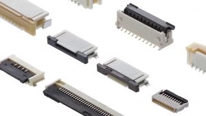
ZIF (Zero Insertion Force) Termination – A style of termination that allows a flex circuit tail or tab to be inserted into a circuit board mounted connector. After insertion a mechanical actuator locks the flex in place.