How to Choose the Right Dome for a Membrane Switch

How to Choose the Right Dome for a Membrane Switch

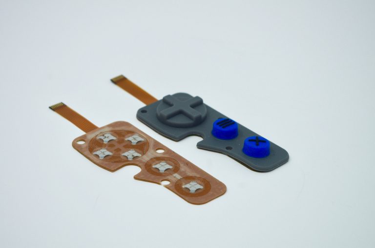
Choosing the “right” dome for a membrane switch may seem daunting, but rest assured, it is more straightforward than you might initially think. Firstly, what are metal domes? Metal domes are used in membrane switches and keypads to enable and facilitate the electrical connection from the keypad to the product itself. Or in other words, how the user of a device initiates a specific electrical function on the product. 

Electrical switches are necessary in almost every HMI (human-machine interface) device or product. No membrane switch is the same and all are used in a unique environment, therefore it is critical that the most suitable dome is chosen for the specific application and environment. For instance, if the product is used in an industrial setting and the user will be wearing gloves: a dome larger in size with a higher force & stronger tactile feedback would be ideal. Or if the membrane switch will be used in a nursing home setting and the user will typically be older in age: a dome with a lighter force (easier to press) would be best suited.

Our CSI engineers will work closely with you in deciding which dome is best for your application. We understand that the tactile feel of a key is very subjective, so typically will mock up multiple sample keypads with different dome options in the prototype stage of the design. This allows our customers to make a decision through a more “hands-on” approach. It’s also important to understand that the dome happens to be one of the easiest components of the membrane switch design to change-out & replace throughout the design cycle and even after the keypad is in production (ie so you are never stuck with a specific dome).

Dome Characteristics & Options:
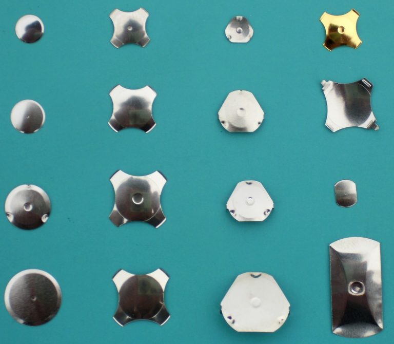
Size: 

Measured in diameter and height of the dome. The size of the keys on the membrane switch will ultimately determine the size of the dome required for the application. Domes sizes range from 6mm up to 20mm. Height is dependent on size and ranges from .25mm up to 1.45mm.
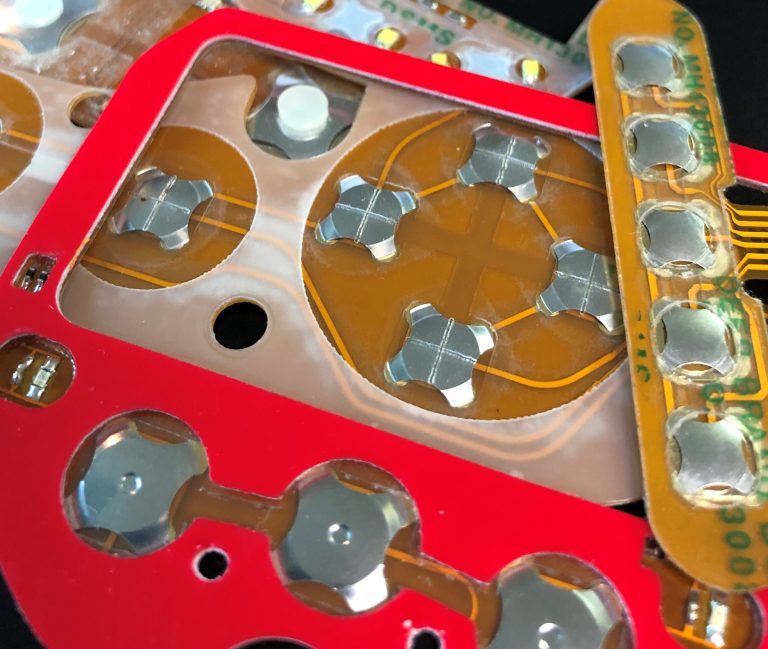
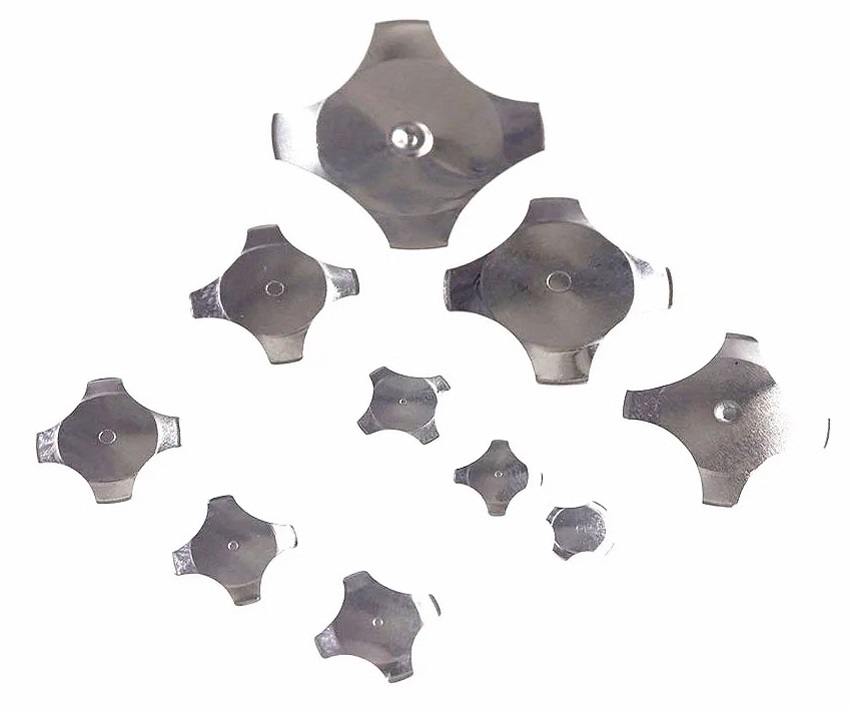
Shape:

  • Four legged
  • Triangle
  • Round 
  • Oblong
  • Custom
 

Actuation Force: 

The actuation force is one of the most critical characteristics when choosing a dome. Actuation or trip force is the minimum force needed to depress the dome and is measured in grams. Actuation forces range from 40g up to 2250g. 

Lifecycles: 

Domes have come a long way since their inception. Originally, domes were only rated for thousands of cycles. The standard for domes is now at least one million cycles, with specialized domes rated for at least five million cycles. No matter the application, there is a dome that can meet your lifecycle requirements.

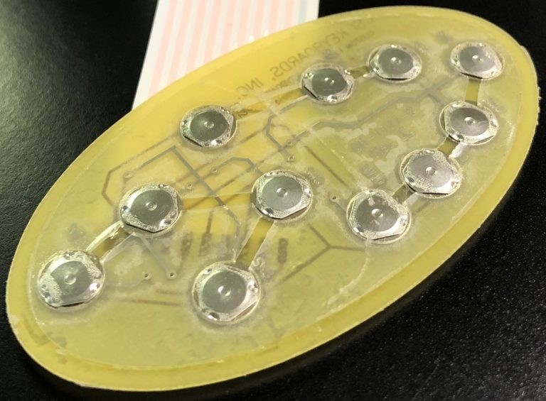
Dimple or Non-Dimpled: 

Looking at a variety of domes for different applications, users may notice a little dimple located in the center of the dome (see pictures to the right). The dimple is a small concave feature located on top of the dome, and can be as deep as 0.2 mm (0.008 in.). The purpose of the dimple is to provide better electrical characteristics and to reduce contact bounce..

Choosing the Best Materials for a Membrane Switch Design

Choosing the Best Materials for a Membrane Switch Design

Designing a membrane switch can be a daunting task at times especially when it comes to choosing the best materials for your membrane switch design. There are many different  materials to consider when designing the keypad. Below you will find some of the standard materials and components CSI typically uses in our membrane switch designs.

Polyester


  • The material of choice for membrane keypad overlays due to its superior flex life and chemical resistance

  • Most common thicknesses are .006”, .007”, .008” and .010”

  • Certain films are suitable for outdoor use with UV inhibitors for resistance to the UV effects of sunlight.

  • Available with built-in Microban antimicrobial protection that inhibits growth of bacterial, mold & mildew.

  • Also available in brushed finish to simulate the look of brushed metal

  • Special “soft touch” surface finish available to mimic the feel of silicone rubber


Polyester Products

Polycarbonate

  • Ideal for standalone display windows, overlays without keypads as well as bezel overlays for rubber keypads

  • Available in textured, antiglare and glossy finishes

  • Certain films are suitable for outdoor use with UV inhibitors for resistance to the UV effects of sunlight.

  • Available in an anti-fog coating

  • Available in thickness ranges from .005” to .030”


Polycarbonate Products

Adhesives

3M 200MP High Performance Adhesives

  • Suitable for high surface energy materials such as aluminum, steel, polycarbonate, ABS, nylon, etc.

  • Widely used in the membrane switch applications

  • Available in thicknesses of .002” and .005”. For adhesion to textured surfaces the .005” thickness is recommended.

  • Service temperature range of -31°F to +300°F for prolonged periods and +400°F for short periods.

  • Excellent environmental, temperature, chemical and humidity resistance


3M 300LSE High Strength Adhesives

  • Ideal for adhesion to low surface energy plastics such as powder coated paint and polypropylene

  • Available I nthicknesses of .002”, .0035”, and .005”. For adhesion to textured surfaces the .005” thickness is recommended.

  • Service temperature range of -40°F to +200°F for prolonged periods and +300°F for short periods.

  • Excellent environmental, temperature, chemical and humidity resistance.

Membrane Switch Components
 
 Connector Pins
 
Connector Housings (used in conjunction with Pins)
 
Metal Domes
 
LEDs
 
Support Panel Fasteners
 
Fiber Optic Lamps

What Does Quality Mean to CSI Keyboards?

What Does Quality Mean to CSI Keyboards?

CSI Keyboards’ Quality Department has developed a quality structure to drive continuous improvement. CSI continuously strives to improve our quality across all facets of our business, including and not limited to: design and engineering, sales and customer service, throughput, and manufacturing.

Each employee at CSI Keyboards is committed to doing whatever it takes to produce the highest quality products delivered on-time. As a global leading keypad manufacturer, CSI employees takes an active role in ensuring that the parts we design, manufacture, assemble and produce are of the highest quality. Testing is a crucial part of our manufacturing process, hence all of our products are tested 100% both electrically and cosmetically before they are carefully packaged and shipped to our customers.

ISO 9001: 2015 Certified

As our further commitment to quality, CSI Keyboards, Inc. is ISO 9001: 2015 certified. ISO 9000 is a series of quality management systems standards created by the International Organization for Standardization (ISO), a federation of 162 member countries based in Geneva, Switzerland. The American National Standards Institute (ANSI) is the member body representing the United States. ISO 9001:2015 is a comprehensive Standard in the ISO series, covering design, manufacturing and, most importantly, customer focus. The ISO 9001: 2015 certification is a testament to CSI Keyboards’ continued commitment to quality and service in the design and manufacturing of membrane keypads and user interfaces.

Things to Consider When Designing a Membrane Switch

Things to Consider When Designing a Membrane Switch

Designing a membrane switch can be overwhelming at times. There are many different design choices, materials, and other considerations to think about when designing the keypad. For these reasons, CSI typically recommends creating prototypes before entering production. Prototypes allow our customers to have working samples that they’re able to test the look, feel, and functionality. 

Below you will find some important design items to consider during the membrane switch design phase.

Membrane Switch Materials

From molded rubber keypads to standard polyester overlay membrane switches, there are a variety of materials and substrates to consider based on the type of membrane switch requirements. Membrane switches range from PCB membrane switch keypads to flexible circuit membrane switches.

Membrane Switch Circuitry

The circuit layer is a critical component of the membrane switch assembly. It’s the circuit layer (or layers) that enable the device’s connectivity. The choice between integrating a printed circuit board or flexible circuit depends on the product and the requirements. If the membrane switch calls for a flexible circuit, the decision on whether to use printed silver or copper flex also must be made.

Membrane Switch Backers

Rigid backers, such as aluminum or G10, can be integrated into the membrane switch assembly in order to provide rigidity or structure. 

Membrane Switch Backlighting & LED Integration

Backlighting is an important consideration in membrane switch prototype design. For products that will be used in dim lighting conditions, backlighting adds usability to a product’s user interface. There are several backlighting options that may be used in membrane switch prototype design, including embedded LEDs, light guide film technology, fiber optic backlighting, and electroluminescent (EL) backlighting. 

LEDs can also be integrated into the membrane switch assembly for simple indicators. 

Graphic Overlays

The graphic overlay is the visual interface component of a membrane switch assembly, providing the look and feel of the final product. Graphic overlays can be screen printed or digitally printed, based on the desired effects. Digital printing provides some key advantages in the printing of graphic overlays such as a broader range of effects, including photo-quality printing. Textures, embossed areas, transparent windows, backlighting, and dead front or white front images are all considerations in designing the graphic overlay component of a membrane switch assembly.

Tactile Feedback

Tactile feedback plays an increasingly important role in product usability, as tactile feedback options have evolved from the traditional feedback provided by standard keypads to a variety of feedback options with varying actuation force requirements. Tactile feedback can be created with the use of stainless steel domes in the membrane switch assembly. 

EMI/RFI Shielding

Electromagnetic Interference (EMI) and Radio Frequency Interference (RFI) are two terms that are often used interchangeably. EMI and RFI disturbances can both have a serious impact on the functionality of an electronic circuit. EMI/RFI shielding is a process that protects the circuits from this interference from other devices or influences, ensuring the longevity of a device by reducing interference through the use of magnetic or conductive materials that block the field.

Designing a Waterproof (IP67) Membrane Switch

Designing a Waterproof (IP67) Membrane Switch

Many customers reach out to CSI Keyboards with a waterproof IP67 requirement for their membrane switch or user interface. CSI utilizes a few different design techniques in order to waterproof a membrane switch which include utilizing a frame seal gasket, the use of copper flex circuitry, and the use of high performance adhesives. There are other methods and ways of waterproofing that can also be integrated into the design, but the frame seal, the type of circuitry and the adhesive used are the foundation to ensuring that your keypad is environmentally sealed. 

Frame Seal Gasket:
 

The Achilles heel for membrane switch sealing is most always the flex tail breakout area. The tail typically breaks out of the rear of the switch and because the tail is made of the same material as the circuit, a filler piece replaces the ribbon cable shape in the materials of the membrane switch. The gaps on either side of this tail filler is typically where moisture can enter the membrane switch.

A gasket or perimeter seal frame design can solve this problem. A membrane switch with a gasket or perimeter seal does not have a tail filler therefore there is no direct pathway for liquid ingress. CSI Keyboards’ perimeter seal frame switches have proven to be as robust as other sealing methods such as perimeter temperature sealing and can be included in your design at minimal additional cost.


  • Construction Concept: Setting the membrane switch circuit within a frame seal gasket, protecting it from the environment.
 
  • Width & Thickness: The thickness of the membrane switch whereby the switch layer printing thickness also taken into consideration, should flush with the gasket making them even as a whole. One whose height is greater than the gasket will budge & cause delamination over time between the product & the interfacing panel, eventually water leakage. The width of the frame seal gasket is also a critical factor dictating the strength of water immerse pressure protection.
 
  • Gasket Adhesive Tape Selection: Not neglecting the gasket, industrial closed cell foam carrier tapes are among the options providing superb adhesion strength.
 
  • Enhancement: For an even more stringent environmental requirement, the conductive printed PET can be substituted with a double-sided through-hole, single conductive print design where the insulator between the two conductive print is the substrate itself, posing an advantage over the insulating dielectric print depreciation between conductive prints of a single sided design when functioning in a high humidity environment.

Copper Flex Circuitry:

CSI Keyboards uses copper flex circuitry in the majority of our custom keypad designs due to its excellent dielectric strength, thermal stability, chemical resistance and flexibility. Copper flex, also known as Kapton circuits, have become the superior choice over printed silver especially for outdoor applications. 

A printed silver circuit can be replaced with a copper and polyimide construction with minimal additional cost. Copper flex circuitry construction designs offer a significant advantage over printed silver. Additional information on the benefits of copper flex circuity can be found here: Benefits of Using Copper Flex Circuitry vs. Printed Silver.

Copper Flex membrane switch panels are produced using polyimide (Kapton) as the base material. Copper flex keypad switches are manufactured by laminating a thin sheet of copper to a flexible film substrate. The copper is then chemically etched away, leaving the copper traces. An additional layer of polyimide is laminated to the circuit leaving the gold contacts exposed.

Front Panel Assembly and Turnkey HMI Solutions

Front Panel Assembly and Turnkey HMI Solutions

CSI Keyboards has over 35 years of experience specializing in the integration of the below technologies into complex user interface turnkey keypad assemblies which has made us the one stop shop for all HMI turnkey interface solutions and front panel input interface assemblies and modules that incorporate electronic components. Our broad product line and engineering expertise allows for us to design and manufacture fully integrated interface solutions at a lower cost and better flexibility for the customer. Customers all over the world rely on CSI Keyboards’ expertise to design, manufacture, and assemble the whole turnkey user interface.

Why turn to CSI to design and manufacture your front panel?

By providing the entire value-added assembly, CSI not only minimizes the amount of moving parts for our customers but also overall time and cost. It also allows our customers the ability to place one single purchase order under one single part number for the entire front panel interface. Our longstanding supplier relationships and over 35 years of manufacturing and assembly expertise provides increased control and lower costs for your company.

From membrane keypads and elastomer rubber assemblies, to touch screens and touch panels integrated with displays, CSI Keyboards specializes in designing and fully integrating a variety of components and customized parts into a complete custom turnkey keypad assembly and user interface for your company. We can take your concepts and bring your product to fruition providing you with the complete plug and play keypad package from one dependable and experienced source. 

Features of an HMI Assembly

Value-Added Membrane Switch Panel and Turnkey User Interface
Fully Loaded PCBs (printed circuit boards)
Integrated Touch Screens
Integrated Displays
Integrated Display Windows
Optical bonding and adhesive bonding for touch screen + display solutions
G10 Backers
Metal Backers
Flexible Circuits
Enclosures and Housings
Bezel Integration and Assembly
Connectors
Cable Assemblies
EMI / ESD / RFI Shielding
Barcode scanners

Integrated Touch Screen and Display Solutions

CSI Keyboards’ Integrated Touch Screen and Display Solutions are second to none, combining our many technologies and utilizing our interface expertise to meet your specific product requirements. CSI is able to provide a full all in one, turnkey touch screen assembly incorporating the touch panel, display, and controller integrated into a bezel, open-framed design, panel mount, or keypad. Using optical bonding or adhesive bonding, CSI Keyboards can provide a fully integrated touch screen + display solution to meet your medical requirements. Our touch screen solutions can then be integrated with a graphic overlay, membrane keypad, rubber switch, or bezel for a complete value added assembly. CSI interfaces are carefully designed and built to survive in any environment. Our touch screen solutions can be sealed to prevent moisture and contaminant ingress and are designed to withstand repeated use and chemical cleaning. Applications include medical, POS, industrial, kiosks, military, retail, gaming, office automation, transportation, and commercial.

Electrical Guide to Membrane Switches

Electrical Guide to Membrane Switches

There are many critical aspects to consider when designing a membrane switch. The electrical portion of the keypad is one of these critical aspects. There are few considerations to consider when laying out the circuit including: the pin out sequence; tail length & position; multilayer circuitry; and use of LEDs. 

Connector Pin Out Sequence: 

CSI produces membrane switches with both row & column matrix, or common ground circuit layouts. Customers should consider allowing CSI to determine the pin out sequence if the sequence is not critical to the customer’s design. Allowing CSI to produce the pin out will result in a superior design including potentially lower cost, higher reliability, shorter lead time.

– Matrix:

A matrix layout is when the circuit is designed in a grid type format using and “X” (rows) and “Y”(columns) axis. The benefit of this layout is there are less tracks allowing for a larger number of connections which then reduces the number of pinouts and connector size. The drawback however is that there are multiple print layers required in order to produce the full circuit.

– Common Bus:

For a common bus layout on a membrane switch one common lead is used for all switch locations. A lead is used to “ground” the circuit. Each switch will have its own individual trace. The benefits of this layout is that only one layer of print is required to complete the circuit. The drawback to this design is it means there is an increase in the number of tracks, pinouts and connector size.

Tail Length & Exit Positioning: 

Membrane switches are typically connected to the customer’s printed circuit board by a flat cable or flex tail. The flexible tail is cut from the circuit layer(s) of the switch. The tail exit position and tail length must be specified before CSI can begin the design of the membrane switch. In volume production tail length, and exit position can substantially affect productions costs. CSI can suggest the best tail exit locations to ensure the most manufacturability is as economical possible. 

Multilayer Circuits: 

Multilayer membrane switches circuits can be designed as screen printed conductive inks on heat stabilized polyester (typically .005”), or with circuit boards. With screen printing technology, multiple circuit layers are created (if necessary to achieve needed trace routing) with dielectric insulating ink printed in areas where circuits cross over one another. With flexible or rigid printed circuit boards feed throughs are used to: create multiple circuit layers, as well as to produce two sided circuits.

LEDs:

Light emitting diodes or LED’s are typically assembled to a circuit layer that lies below the static layer that carries the key functionality due to vertical height issues and space constraints. The tail from the upper layer provides the key interface, while a second tail from the lower layer supplies power for the LED’s. In some cases CSI can include light emitting diodes and key functionality on the same layer, and through the same connector, thereby eliminating the cost of the second circuit layer, and connector.

The Importance of the Graphic Overlay in a Membrane Switch

The Importance of the Graphic Overlay in a Membrane Switch

A membrane switch is the interface that connects the user to a machine, device, or other types of equipment. It is the control panel, facilitating functionality and enabling the user to control the product.

The graphic overlay is one of the most important aspects of the membrane switch. The graphic overlay is the faceplate to the membrane switch and often the product itself. The graphic overlay defines a product’s identity and is the visual layout and design of the interface that determines how easy or difficult a device is for the average user to operate. 

CSI Keyboards is in a class of its own when it comes to the design and production of high quality Graphic Overlays, Labels, and Nameplates. We have been manufacturing overlay products for a wide array of customers and industries for over 35 years. A graphic overlay not only enhances the aesthetic appearance of a product or device, but it can also provide environmental protection. A graphic overlay can also be applied to an assembly using discrete switches or laminated to a membrane or rubber switch depending on the design. CSI offers both silk screened and digitally printed overlays and labels in wide range of shapes, sizes, colors and finishes.  

Critical Features of the Graphic Overlay:

Environmental Conditions

You likely know what type of environment your product is going to end up in. Are there going to be some obvious environmental concerns? If so, it is critical that the right graphic overlay material is designed into your product, since different materials offer different environmental advantages.

Enhancing Usability

Usability is the ultimate goal of a user interface. The features of the graphic overlay can be used to enhance the overall usability of your product. By making the graphic overlay easier to feel, operate, and understand, raised buttons and embossed features can dramatically enhance its functionality. 

Building Your Brand

The visual impact of the graphic overlay cannot be underestimated. The graphic overlay is the faceplate to the membrane switch and often the product itself. The graphic overlay defines a product’s identity and is the visual layout and design of the interface that determines how easy or difficult a device is for the average user to operate. Based on our 35 plus years of experience, we can choose the ideal ink technologies and materials to deliver specialized textures, finishes, and colors. This allows you to create on-brand graphic treatments, powerful visual differentiation, and market-appropriate design cues. With specialized inks, we can match proprietary brand colors. With the right material, we can deliver the right texture and finish, from matte to high gloss. Add in transparent qualities and vibrant base colors, and you can start to see how may options you really have.

Digital printing gives us even more design freedom, in a very cost-effective way. With these technologies, we can reproduce photographs onto the graphic overlay, allowing you to specify any type of background pattern. Brushed aluminum or carbon fiber patterns for more sophisticated applications

Graphic Overlay Capabilities:

Surface Finishes:

  • Velvet
  • Gloss
  • Anti-reflective
  • Anti-microbial
 

Printing:

  • Screen printing 
  • Digital printing
 

Window Options:

  • Clear LCD or LED
  • ITO using optical clear lamination
  • Dead front
  • Smoked as well as translucent colors for backlighting
 

Embossing & Forming:

  • Finger guide, LED, braille, rim, pillow either as a standalone or combination of
  • Cold and hot embossing
  • Hydroforming
 

Cutting:

  • Laser traced steel rule dies
  • Tinplate high precision tools
  • Laser and CNC cutting

Polyester vs. Polycarbonate in Membrane Switches

Polyester vs. Polycarbonate in Membrane Switches

One of the most common questions asked when designing a membrane switch is: should I use polyester or polycarbonate material? There was a time when polycarbonate was the standard for membrane switches, but that has certainly changed over the years. Polyester has since become the industry standard and is what CSI recommends for the majority of our designs. 

Circuit Layers: For the membrane switch circuit layers, polyester is always used as it works best with the higher temperatures that are required for conductive printing. Polyester can be heat stabilized so that it can withstand the any potential for shrinkage during processing.

Graphic Overlay: The choice between polyester and polycarbonate really appears when designing the graphic layer. Embossing the keys gives a better user experience and a nicer look, this is where polyester shines and many think this is the biggest advantage that it has over polycarbonate. Embossing will stress any material (polyester or polycarbonate), affecting it’s life, but polyester can handle this much better than polycarbonate. In fact, it is not recommended to emboss polycarbonate as it can lead to cracking, reduced life, and even failure.

Durability and Chemical & UV Resistance: Polyester also has a greater resistance to chemical and UV exposure. This is critical for any membrane switch that is used in an outdoor or other harsh environment.

Dielectric Resistance: Both polyester and polycarbonate have good dielectric resistance but polyester is typically slightly better.

Preventing Membrane Switch Failures

Preventing Membrane Switch Failures

A lot of time and effort go into designing and manufacturing membrane switches, so it can be such a shame if the final product is not properly handled or assembled upon completion. Typically, the number one cause of keypad failures is in fact improper handling or assembly. 

Here are a few quick prevention tips to help you avoid damaging your membrane switches:

1. Key Pressing: Do not press the domes or keys in the air or unsupported as this will result in dome damage (such as bent domes). If a key feels “dead” or “flat”, it’s usually due to a bent and damaged dome. Ensure the membrane switch is on a flat and rigid surface when pressing any of the keys. 

2. Bending or Flexing: Never bend or overly flex a membrane switch. Bending the switch can damage critical components on the circuit such as domes, LEDs, etc.

3. Creasing Circuit Tails: Avoid creasing a printed silver circuit tail. The creasing of a silver flexible circuit will most assuredly cause the silver ink to crack. Copper flex circuity is more forgiving and allows for creasing, more on that here.

4. Keypad Surface: Ensure that the surface (the keypad is being applied to) is clean and debris-free prior to membrane switch application. It’s always great assembly practice to clean the surface with isopopyl alcohol prior to adhering the membrane switch to your assembly.

Membrane Switch Copper Flex Circuitry