Dead Front Membrane Switch Integration

Dead Front Membrane Switch Integration

Looking to make your membrane switch or only portions of your membrane switch visible only when lit?  You’ve come to the right place. CSI Keyboards has been integrating dead front technology into our keypads and user interfaces for over 35 years.

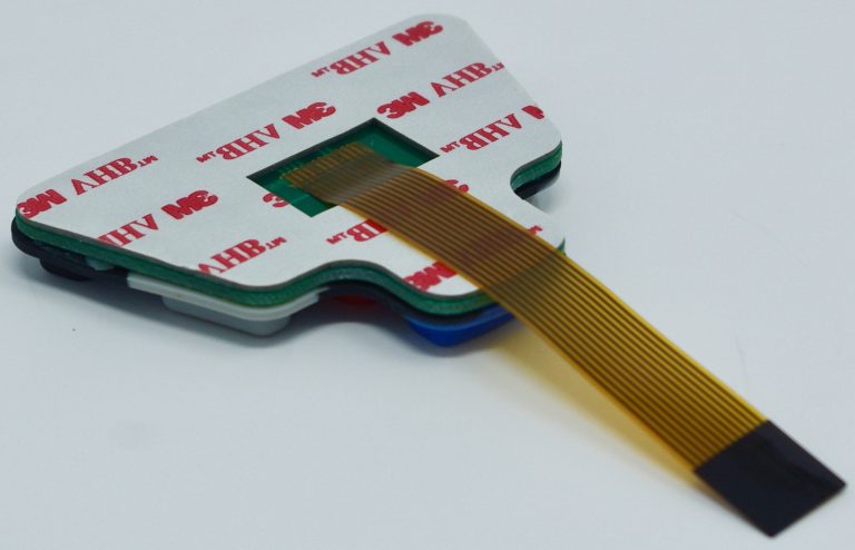
CSI Keyboards manufactures dead front membrane switches and backlit overlays that deliver sleek and intuitive interfaces at a very reasonable price point. Icons and/or nomenclature stay dark/invisible to the user’s eye until the membrane switch backlighting is activated. CSI’s thin backlighting technology can be integrated inexpensively into new designs or product upgrades using various flexible or rigid graphic layer materials.

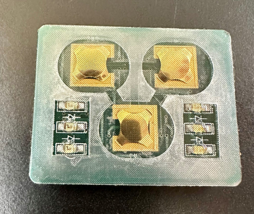
Dead front membrane switches can be created with either printed inks or by adding diffusing layers to the membrane switch itself. Successful integration of the graphic overlay with the membrane switch electronics dictates a custom membrane switch for almost all applications.

Dead front membrane switches can be produced in rich color to promote your brand or increase product aesthetics. Dead front membrane switches can be produced with almost any background color with black being the most common. You can incorporate just one LED light color or have multiple LED light colors within a single display.


Advantages of Using Light Guide Film for Backlighting Membrane Switches​

Advantages of Using Light Guide Film for Backlighting Membrane Switches

Light Guide Film is designed to evenly distribute light from top or side firing LEDs, providing bright, uniformed illumination. It also reduces the amount of LEDs needed, saving power consumption. More on light guide film technology below. The design and utilization of light guide film (LGF) technology has become one of the most common methods of interface backlighting. CSI Keyboards uses proprietary techniques to design the light guide film so it is optimized for light redirection and reflection giving the customer the brightest possible backlighting solution. Light guide film dots are also designed and implemented which allow for the optimization of light distribution to obtain maximum brightness and uniformity. Common problems that many of our competitors face are light leakage and hot spots. CSI’s backlighting designs prevent any light leakage and hot spots from occurring, and also result in much brighter light guide film and interface.

The design typically consists of 1-4 side-firing LEDs as the light source. Hot pressing optical patterns or micro lens on the surface of the PC film to refract lights guided by the PC film. It can be easily assembled with dome switch or molded in keypad. 

The Features and Advantages of Light Guide Film are as follows:

Slim & Sleek Design

1. PC/PU/TPU film with optical pattern design (.125 – .30 mm thick)

2. Surface light source

3. High uniformed brightness

Cost

1. 50% cheaper than EL panels

2. 40% cheaper than using standalone LEDs

Energy Consumption

1. 6 LEDs light: 90mA. (LED: 15mA/pcs)

2 . LEDs + LGF: 40mA. (LED: 20mA/pcs)

Durability

1. LED light source offers 50,000 hours of life.

2. PC film is extremely durable and can function in bothhigh or low temperatures.

Use the Light Guide Film (LGF) for Keypads or LCD backlighting allows for backlighting only where needed. The CSI solution allows for uniform distribution of light regardless of the distance from LEDs. It also allows for segmentation of areas to avoid light leakage between areas or colors.

What Industries Use Membrane Switches?​

What Industries Use Membrane Switches?

CSI Keyboards designs and manufactures user and human machine interface products for a wide variety of industries. CSI has designed keypads that are used in medical instrumentation designed to be sealed from moisture and contaminants. Our membrane switches are also utilized in industries such as electronic test and telecommunication networking equipment. Industrial controls and fitness equipment are also industries where membrane switches are the user interface of choice. We have produced keypads for the military which help save lives overseas, as well as keypads for medical equipment to help save lives here at home. CSI has also developed and manufactured products to be used out on the sea, and others for air and space travel. CSI has designed and assembled custom food equipment keypads, custom lighting control keypads, custom appliance keypads, CAN/BUS custom keypads, custom automotive keypads, and custom fitness keypads. 

No matter the industry or application, we are always eager to demonstrate our extensive capabilities as one of the top keyboard manufacturers in the world. Below is a list of some of the industries that we have served over the last 35+ years:

  1. Medical
  2. Military
  3. Industrial Controls
  4. Aerospace
  5. Marine Navigation
  6. Lighting & Lighting Controls
  7. CAN/BUS Controls
  8. Food Equipment
  9. Appliance
  10. Automotive
  11. Fitness
  12. Sporting goods

Standard Environmental Specifications for Membrane Switches

Standard Environmental Specifications for Membrane Switches

Due to the customized nature and the wide variety of membrane switch designs, it can be somewhat challenging to outline a general set of specifications that covers all membrane switches.  We’ve done our best to to listed below some basic environmental specifications.

  • Humidity: 0 to 98%, no condensation
  • Operating Temperature: -28.9°C (-20°F) to +70°C (+158°F)
  • Storage Temperature: -40°C (-40°F) to 70°C (+158°F)
  • Salt Fog: 5% salt solution, 48 hours
 

It is important to understand the above standard environmental specifications when designing your membrane switch. Environmental factors are a critical aspect of not only the keypad but the end product itself. Many of CSI Keyboards’ customers require environmentally sealed switches and keypads built to last in extreme and harsh environments. CSI Keyboards has over 35 years of experience designing keypads that are completely environmentally sealed and switches that need to meet specific requirements for Water, Temperature, Humidity, Dirt, Dust, Altitude, Impact resistance, Vibration, and Chemical resistance.

Some of our technologies for environmentally sealing keypads include the Seal Frame design, rubber keypad sealing designs, copper flex circuitry, environmentally resistant polyester technology, and other proprietary sealing techniques.  More information can be found in our Environmental Sealing section of the website.

Membrane Switch Overlay Material Guide

Membrane Switch Overlay Material Guide

Due to the customized nature of membrane switch designs, it can be somewhat challenging to choose the proper overlay material. There are a few major factors that must be considered when choosing the overlay material including but not limited to the finish, thickness, and environment. CSI has outlined the materials in the guide below to make this process easier and less daunting.

Venting Membrane Switches: How is it Done?

Venting Membrane Switches: How is it Done?

Venting: 

When a key is pressed in a membrane switch, the air pressure within the switch cavity increases. In order for the switch to close properly, air within
a switch cavity must be displaced, equalizing the internal pressure. There are two standard venting methods that can solve this issue:

Internal Venting: 

Designing narrow channels between key location cutouts (in the spacer layer) allowing the air from one key to move to another key locatoin when that key is pressed. 

External Venting: 

Similar to internal venting, narrow channels between keys are cut into the spacer layer. These channels then exit through the sides, rear, or internal cut-outs of the membrane switch. External venting is not recommended for membrane switches exposed to harsh environments, as there is a greater risk of contamination

Standard Electrical Specifications for Membrane Switches

Standard Electrical Specifications for Membrane Switches

Due to the customized nature and the wide variety of membrane switch designs, it can be somewhat challenging to outline a general set of specifications that covers all membrane switches.  We’ve done our best to to listed below some basic electrical performance specifications.

  • Contact Material: silver, carbon, gold or nickel
  • Voltage: 30 volts DC
  • Rated Current/Voltage: 20mA@30 volts DC resistive load
  • Contact Bounce: < 20 milliseconds
  • Loop Resistance: The loop resistance of a switch is a function of trace width and length. In most applications the maximum loop resistance is less than 100 ohms.
  • Dielectric Strength: 5000V max on polyester material 
  • Open Circuit Resistance: 10 ohms
  • Capacitance: 20 picofarads
  • Maximum Switch Power: 1 watt
  • Design Configuration (illustrated below): Common Bus, XY Matrix, or Custom

Shielding Options for Membrane Switches

Shielding Options for Membrane Switches

Depending on the type of membrane switch design, the graphic overlay material or the molded rubber materials both have a relatively high dielectric strength and high volume resistivity. If required, a higher degree of electrical shielding can also be integrated into the membrane switch construction. The requirements can vary depending on the industry the product will be used in. 

Shields can be designed for the following:

  • ESD (Electrostatic Discharge)
  • EMI (Electromagnetic Interface)
  • RFI (Radio Frequency Interface)
 

CSI offers four shielding methods to protect membrane switches:

  • Foil: Laminated aluminum foil and polyester.
  • Transparent Film: Shielding required over windows (more costly).
  • Printed Screen: printed with silver conductive ink in a grid, bus-bar or full-coating format. Typically, the grid format is chosen because it is very reliable and does not use as much silver conductive ink as does the full-coating format.
  • EMI Mesh: The mesh is die-cut to the shape of the keypad and then assembled into the internal layers of the keypad assembly.
Membrane Switch with EMI Mesh

Shield Termination Methods:

  • Tab: The preferred method for reliability. Can be attached to a stud or stand-off on a back panel or metal enclosure.
  • Connector:  Shield layer can be terminated into a pin or pins on the circuit tail connector.
  • Wrap-Around: Shield layer can wrap completely around the membrane on all four sides to ground to a chassis. Although this method is very reliable, it is more costly than the other two methods due to the added labor and material necessary to execute. 

Hot Bar Solder Lamination: What is It and Why Utilize It?

Hot Bar Solder Lamination: What is It and Why Utilize It?

Our customers sometimes require a membrane keypad with a connection that calls for flex circuits directly connected to rigid boards versus using connectors. Connecting a flexible circuit directly to a printed circuit board requires a manufacturing procedure called hot bar solder or heat seal lamination. There are many benefits for using a direct flex-to-board connection. 

The Main Benefits of Hot Bar Solder Lamination:

1. Saves vertical height in the design

2. Fast temperature ramp-up and cool-down 

3. Closed loop temperature control

4. Can be more reliable than fine pitch connectors

5. Accurate positioning of the parts

6. Multiple connections can be made simultaneously

7. Cost effective due to elimination of third component such as connector

ZIF Connectors on Membrane Switches: What Are They, What Do They Do?

ZIF Connectors on Membrane Switches: What are They & What do They do?

ZIF connectors have no physical connector on your membrane switch and rely on a receptacle connector that is available from numerous manufacturers. It is important to choose a ZIF connector that is suggested for membrane switches and to keep in mind that smaller pitches are available in polyimide flexible printed circuits only.

ZIF connectors are increasingly common in several applications, especially when connecting to a small display or keyboard. ZIF connectors meet a range of requirements including low profile, lightweight, secure, and removable connections. ZIF connectors are appropriate for more complex applications and allow for higher levels of integration. For ZIF connections, the connector system is not on the membrane tail, but on the PCB. The tail of the circuit is inserted into the ZIF connector to create the contact, and a stiffener is laminated under the tail to ensure stability and maintenance of the electrical contact. ZIF connectors may have anywhere from 2 to 30 positions on a single row, and distances of between 1mm and 2.54 mm are available.

Keep in mind that ZIF connections degrade with insertions, so the maximum number of insertions should not exceed 10 cycles. It’s also important to remember to take care when placing the tail die but in relation to the printed traces, since resistance in the circuit may increase in spacing of less than 1mm where the circuit traces are thinner.